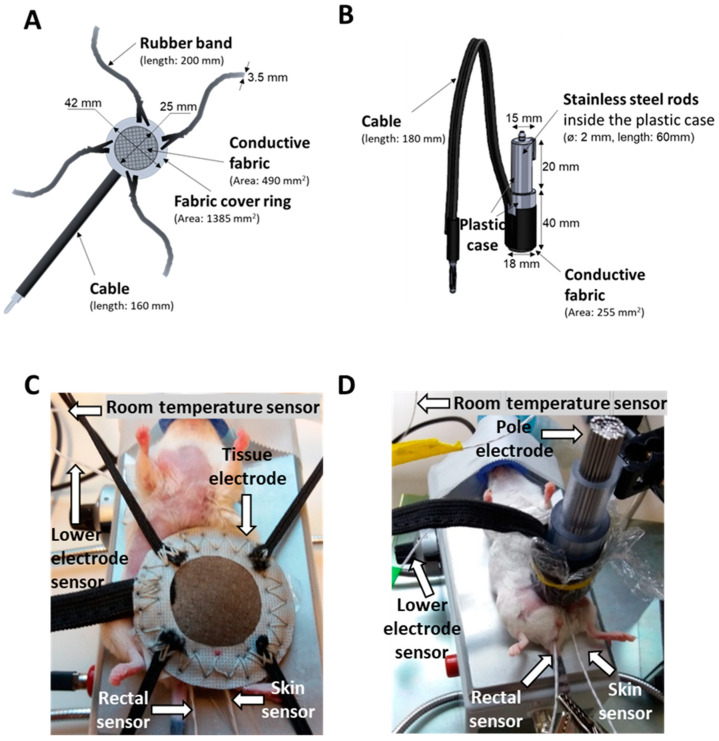
Figure 12.
Comparison of the mEHT treatment setups. Schematic diagram and dimensions of the (A,C) previously used tissue electrode and (B,D) improved pole electrode. Animal on the lower electrode with (A,C) the tissue electrode and (B,D) the pole electrode. The electromagnetic field was established between the lower electrode and the upper electrode positioned on the tumor. The temperature at the four locations is monitored by temperature sensors (rectal, skin, lower electrode, and background).

