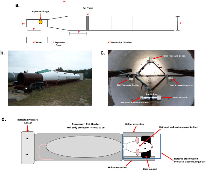
Figure 8.
Blast tube parameters. (a) A diagrammatic scheme of the blast-tube used for this study. (b) The exterior aspect of the explosive-driven blast-tube used for this experiment. (c) A cross section of the inside of the BWG at the level of the rat holder and pressure gauges. This picture is
taken from the perspective of the explosive charge located in the driver section of the BWG. In this picture, the rat holder is placed on the lower corner of the frame; disk pressure gauges are placed on the remaining three corners for the recording of incident (side-on) pressure. A “face-on” gauge, for the recording of reflected pressure, is fitted at the tail end of the rat holder (visible as a small spot at the left end of the holder in the picture). Rat holder and pressure gauges are equidistant from the explosive charge. During the actual blast exposures, rats were placed 2 at a time in the frame at the top and bottom vertices with the disk pressure gauges on the right and left vertices. (d) Schematic of the aluminum rat holder and rat position within the holder from the perspective of the explosive charge.

