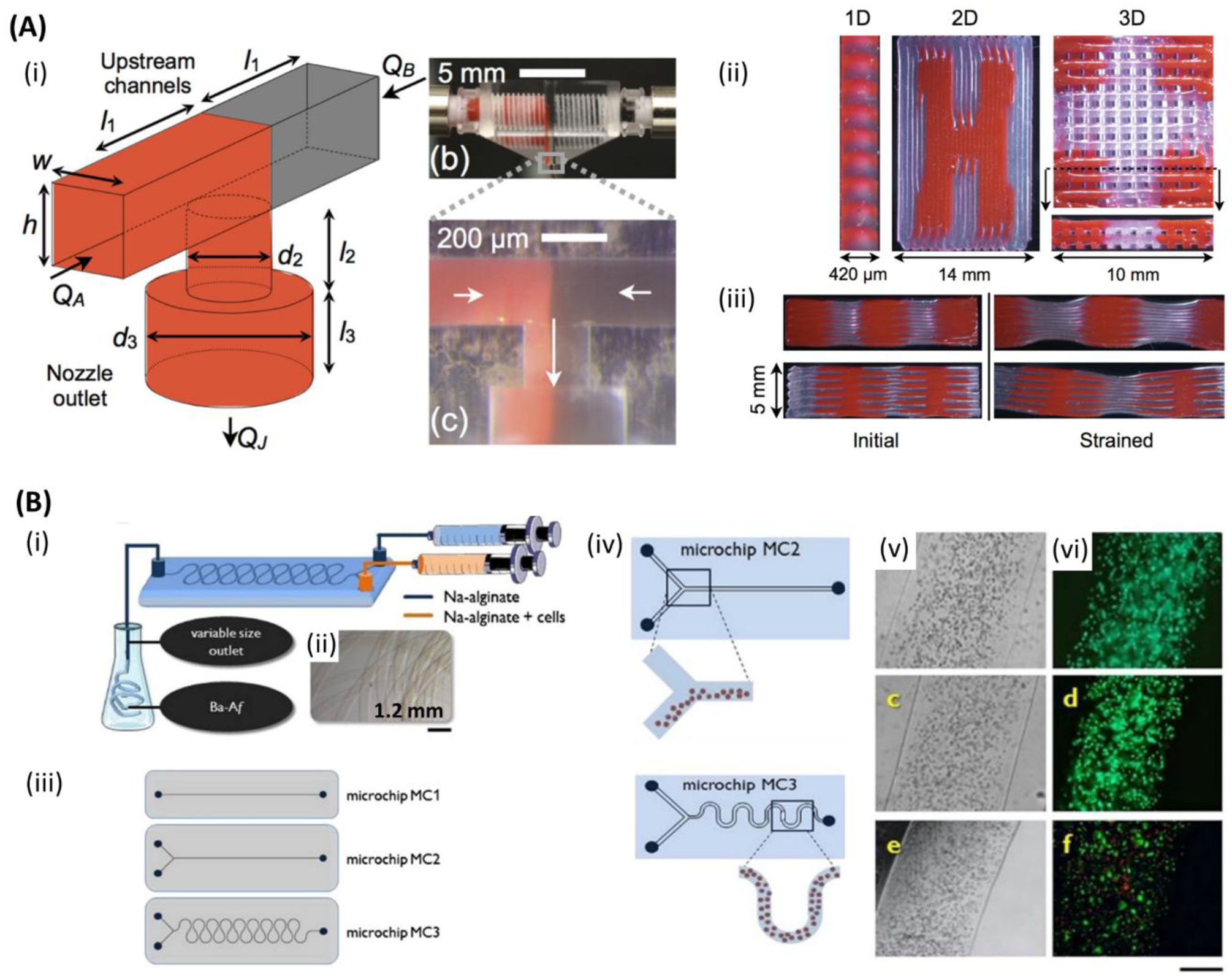
Figure 4.

Microfluidic bioprinting chips. A) (i) Schematic of a microfluidic printhead for multimaterial printing with controlled flow rate of each material by independently actuated syringe pumps. (ii) One-, two-, and three-dimensional (1D, 2D, and 3D) printed multimaterial PDMS (red and clear) structures. (iii) Cross-section images of two different multimaterial 3D structures with different stiffness. Initial form of the structures (left), and after applying strain (right). Reproduced with permission.[184] Copyright 2015, WILEY-VCH Verlag GmbH & Co. B) (i) Schematic of the microfluidic chip for alginate microfibers formation. (ii) Micrograph image of the alginate microfiber formed by microfluidic chip. (iii) One and two inlets straight channel microfluidic chips (top and middle) and two inlets snake-shape channel micromixing chip (bottom) for cell-laden alginate microfibers formation. (iv) Schematic of segregated vs homogenous cell distribution within alginate microfibers when employing straight channel and snake-shape channel microchips. (v) Optical and (vi) fluorescent images of sarcoma osteogenic (SaOS-2) osteoblast-like cells laden in alginate microfibers after 1 day (top (both)), 7 days (middle (both)), and 14 days (bottom (both)). (green: live; red: dead). Scale bar: 250 μm. Reproduced with permission.[181] Copyright 2015, Elsevier.
