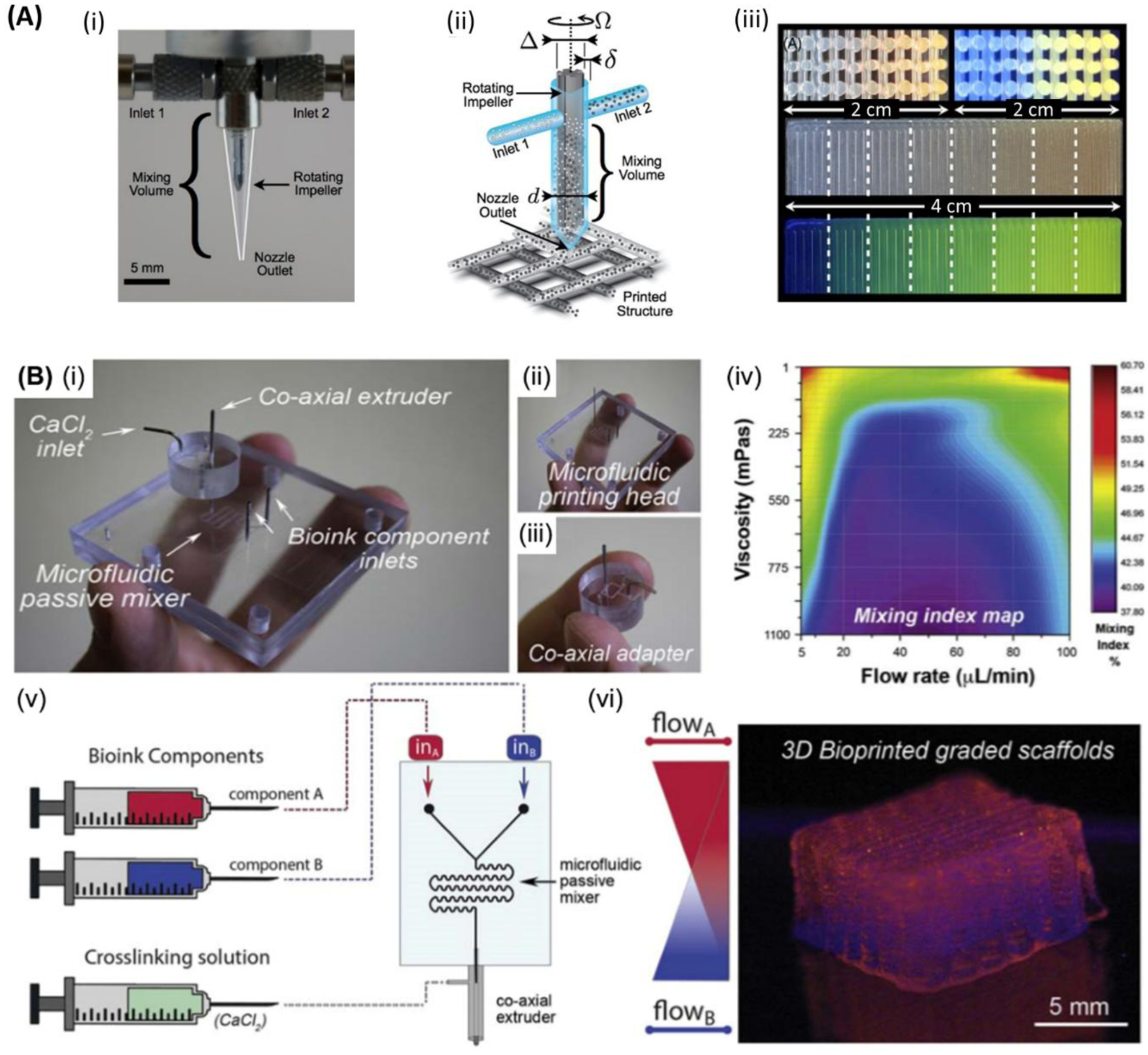
Figure 9.

Graded structure bioprinting. A) (i) Optical image of an impeller-based mixer. (ii) Schematic of a mixing nozzle for active homogenization of two inks entered through inlets #1 and #2 for three-dimensional (3D) printing of constructs of multiple materials. (iii) Cross-section images of 3D lattice constructs showing the continuous variation of the fluorescent pigment concentration under bright light (top left) and UV light (top right). 2D structures showing the discrete variation of fluorescent under 8 different mixing ratios under bright light (middle), and UV light (bottom), respectively. Scale bars: (i) 5mm. Reproduced with permission.[192] Copyright 2015, American Physical Society. B) (i) Microfluidic extrusion system composed of (ii) the microfluidic printing head and (iii) the co-axial adapter. (iv) Mixing index heatmap is shown. In (v) and (vi) the schematic of the fabrication process and the final 3D bioprinted graded scaffold are shown, respectively. Reproduced with permission. [172] Copyright 2019, IOP Publishing.
