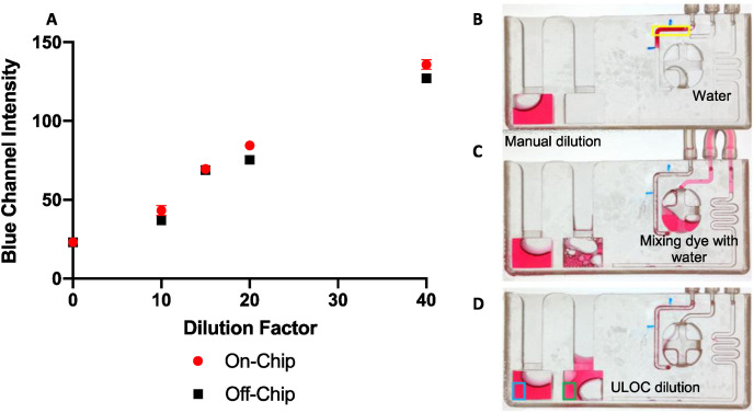
Fig. 5.
ULOC dilutor. (A) Graph depicting the performance of ULOC for unidirectional sample dilution as a function of blue channel intensity. The red circle represents ULOC dilutions. The black square represents manual dilutions. (B) ULOC before dilution, the area where the volume metering reading is taken from is outlined in yellow. (C) ULOC during dilution, the dye mixes with water in the reagent reservoir and is delivered to the test area by the fluidic system. (D) ULOC after dilution, intensity reading for the manual dilution (outlined in blue), and the intensity reading for the ULOC dilution (outlined in green). (For interpretation of the references to color in this figure legend, the reader is referred to the Web version of this article.)

