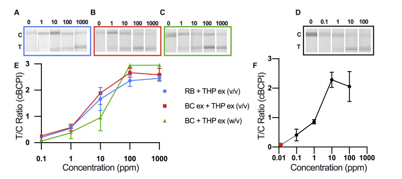
Fig. 6.
Photographs and calibration curves showing LFIA signal development in increasing concentration of analyte where error bars represent standard deviation (n = 3) (A) 1–1000 ppm, total hazelnut protein (THP) extract spiked into running buffer (RB)(v/v); (B) 1–1000 ppm, THP extract spiked into a blank cookie (BC) extract (v/v); (C) 1–1000 ppm, BC spiked with THP extract (w/v); (D) 0.1–100 ppm, BC spiked with hazelnut cookie (HC) (w/w); (E) Calibration curve for [A; blue circle], [B; red square] and [C; green triangle] where circles represent the signal at 0 ppm; (F) Calibration curve for D, red circle represents 0 ppm measurement. (For interpretation of the references to color in this figure legend, the reader is referred to the Web version of this article.)

