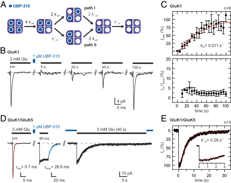
Fig. 3.
Glutamate-induced currents during UBP-310 dissociation. (A) Kinetic scheme showing the different occupancy states that can become populated during antagonist dissociation. Two antagonists may be bound at different LBD dimers (path I) or at the same LBD dimer (path II). More details are provided in SI Appendix, Note 2. (B) Glutamate responses during UBP-310 dissociation from GluK1 homotetramers. Test pulses of 3 mM glutamate were applied before and at 5-s intervals after applying a pulse of 1 μM UBP-310. (C) Peak currents (Top) and steady-state currents (Bottom) normalized to the peak currents before UBP-310 application (mean ± SD, n = 6 patches). Fitting the kinetic scheme in A with k′off = 0.28 s−1 (see below) yields koff = 0.011 s−1 (red line). (D, Left) Glutamate responses of GluK1/GluK5 heteromers. UBP-310 binding at the GluK1 subunits blocks glutamate-induced desensitization. (D, Right) After UBP-310 dissociation, the GluK1 subunits become available for glutamate binding, and the steady-state current slowly desensitizes. (E) The disappearance of the steady-state current (average current of three patches) shows a clear lag phase. Fitting of a three-state kinetic scheme yields a k′off = 0.28 s−1 (red line). Details of the model are provided in SI Appendix, Note 2, and details on the fits are provided in SI Appendix, Fig. S4.

