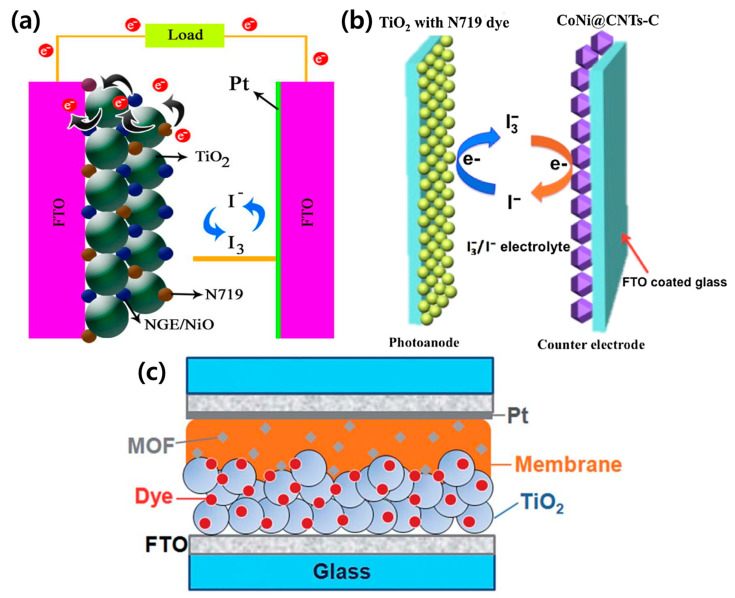
Figure 5.
Schematic of a DSSC configuration using MOFs as the (a) photoanode [85], (b) counter electrode [90], and (c) electrolyte [81]. Reproduced form [81] with permission from The Royal Society of Chemistry. Reprinted from [85] with permission. Copyright© 2017, Elsevier. Reprinted from [90] with permission. Copyright© 2017, Elsevier.

