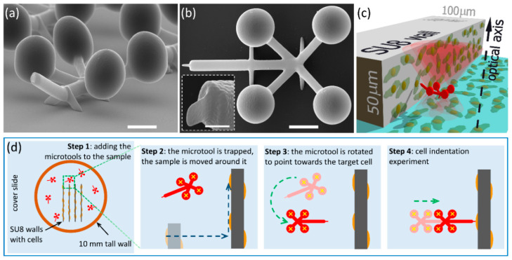
Figure 1.
The polymerized microtool used for cell indentation experiments and the sample arrangement. Scanning electron microscopic images of the microtools: (a) side view and (b) top view (scale bars: 5 μm). It is visible that the tip together with the trapping spheres are at a different plane to the rods connecting them. The insert in (b) shows the side view of the microtool’s tip (scale bar: 1 μm). (c) 3D schematic view of the experimental arrangement: cells are grown on a vertical wall polymerized from SU8 as well as on the glass substrate forming a confluent layer; the microtool (red structure) that is trapped and actuated with the optical tweezers (red cones) is approaching the cells on the wall with a translation that is perpendicular to the optical axis of the system. Panel (d) illustrates the sample assembly process with the microtools (red structures) after being pipetted into the sample well (Step 1) and their alignment towards the target cell (for details see Section 2.4); yellow crosses mark the trap beam positions, dashed blue arrows indicate sample stage movements (Step 2) and dashed green arrows the optical trap actuations (Steps 3 and 4).

