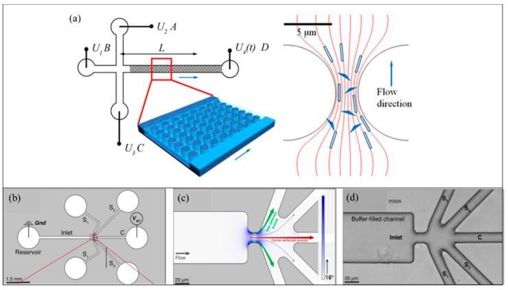
Figure 9.
DNA manipulation using iDEP [121]. (a) Sketch of the microfluidic device (not to scale). Channels linked to reservoirs (A−C) are 1.7 cm long. All the channels have a width of 100 μm and a depth of 10 μm. The length between the post arrays linking to reservoir D along the channel is 2 cm. The distance between the intersection and detection point is L. [121]. (b) Schematic to show the pathways for introducing sample DNA analyte via the left reservoir. From the left reservoir, the analyte enters the constriction via inlet branch and then electric potential is applied to five outlet branches (S1 or S2), and C. Inlet and C outlet reservoirs are inserted with platinum wires [121]. (c) Zoomed in view of the constriction region showing the intensity of electric field gradient color. (d) Bright-field image of the expanded region of the constriction zone in the microdevice [121]. © Figure 9 Reprinted and adapted with permission from [121]. Copyright (2015) American Chemical Society.

