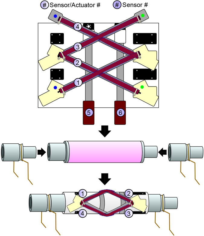
Fig. 2.
Basic layout for the twisting skin and how it fits around the cylindrical structures. The skin is shown unwrapped. In the physical skins, the sensor and actuator pairs with the blue and green dots are sewn at the locations on the skin with matching blue and green dots. The actuators and sensors are labeled for reference. This skin is stretched around the cylindrical structure and leg connectors are applied on either side.

