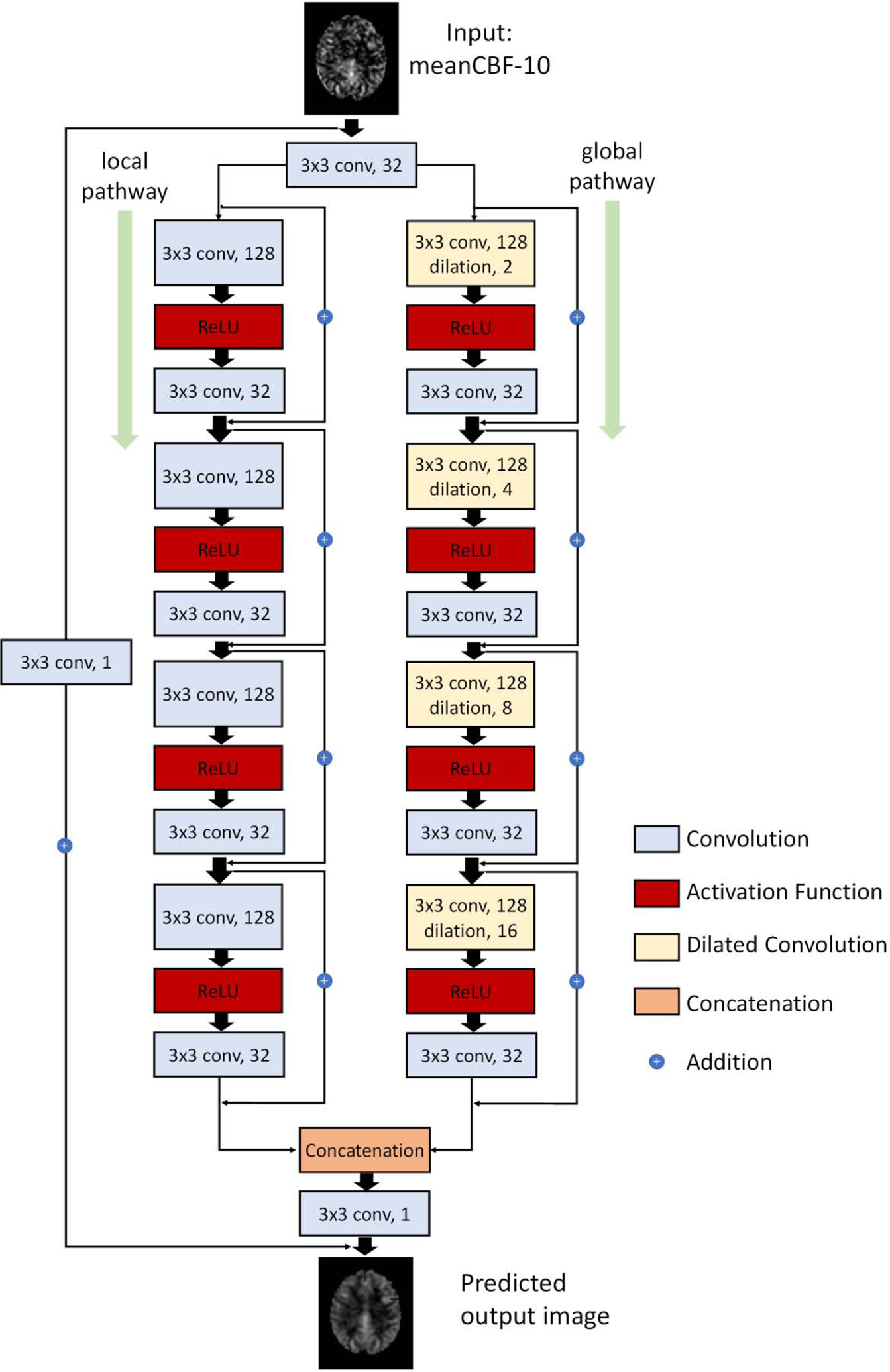
Figure 1.

Schematic illustration of the architecture of our proposed DWAN network. The first layer consists of 3×3×32 convolutional filters for the input image. Then the output of first layer were fed to both local pathway and global pathway. Each pathway contains 4 consecutive wide activation residual blocks. Each wide activation residual blocks contain two convolutional layers (3×3×128 and 3×3×32) and one activation function layer. The 3×3×128 convolutional layers in global pathway were dilated convolutional layers with a dilation rate of 2, 4, 8, 16, respectively. The output of local pathway and global pathway were concatenated and fed to another 3×3×1 convolutional filter. The 3×3×1 convolutional layer was attached to the end to get the predicted output image with additional input from the input image with 3×3×1 convolution. (a×b×c indicates the property of convolution. a×b is the kernel size of one filter and c is the number of the filters).
