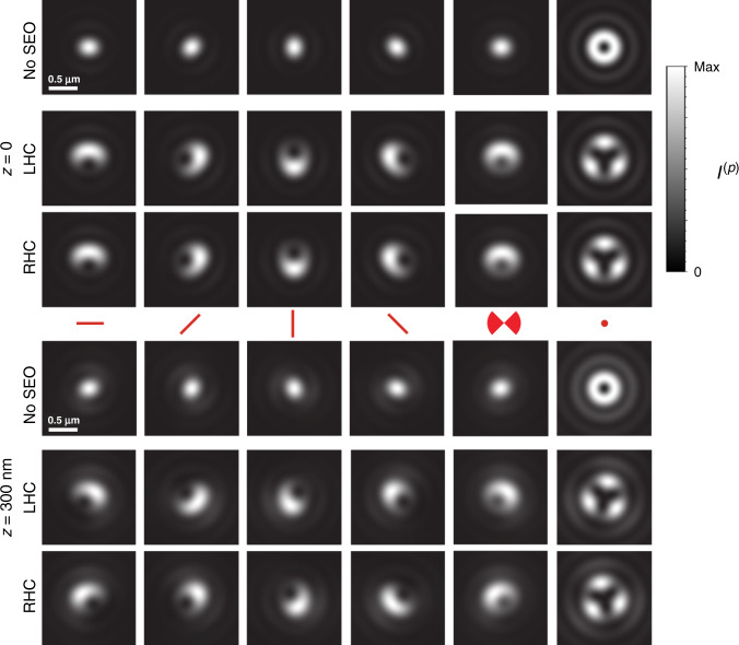
Fig. 3. Theoretical PSFs formed from specific dipole orientation and wobbling.
The PSFs are shown at the nominal focal plane z = 0 (top) and at z = 300 nm (bottom), corresponding to five different dipole orientations: the first four from left to right correspond to nonwobbling dipoles within the xy plane (θ = 90°) and for ξ = 0°, 45°, 90°, and 135°, respectively, while the sixth column corresponds to a nonwobbling dipole in the z direction (θ = 0°). The fifth column corresponds again to ξ = 0°, but for the dipole wobbling within an angle δ of 90° (corresponding to Ω = 0.6π and P3D = 0.6). For both heights, the top row shows for reference the (diffraction-limited) PSFs without the SEO, while the rows labeled RHC and LHC show the two PSFs for CHIDO. Note from the first four columns that a rotation of the dipole within the xy plane causes an approximate joint rotation of both PSFs in a direction opposite to that of the dipole and by twice the angle. A change in height, on the other hand, causes approximate rotations of both PSFs in opposite directions with respect to each other. Wobbling causes a blurring of the PSFs. PSF pairs for other orientations and wobbling angles are shown in Supplementary Movie 1.

