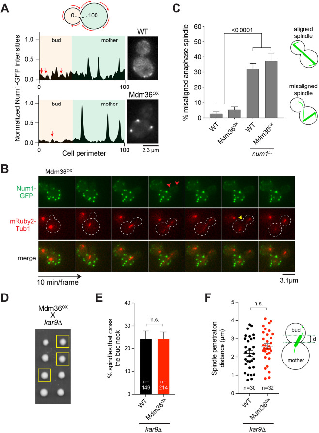
Fig. 2.
Dynein pathway function in Mdm36OX cells. (A) Normalized intensity profile along the cell cortex (left) and single focal plane image (right) of a representative WT and Mdm36OX cell expressing Num1–GFP. Arrows indicate peaks corresponding to dim foci in the bud of both WT and Mdm36OX profiles. (B) Asymmetry of Num1 localization between mother and daughter cell during the budding cycle in the Mdm36OX background. Red arrowheads, dim Num1–GFP patches in the bud; yellow arrowhead, end of mitosis as indicated by spindle disassembly. Dashed lines indicate cell outlines. (C) Percentage of anaphase spindles with a misoriented phenotype for the indicated strains (91≤n≤514 spindles per strain). Error bars represent the standard error of proportion (s.e.p.). P-value calculated using a one-way ANOVA test comparing each strain with every other strain. Alignment phenotypes are presented in the diagram on the right. (D) Representative tetrad progeny of a cross between Mdm36OX (MET3p:MDM36) and kar9Δ. Yellow boxes indicate MET3p:MDM36 kar9Δ progeny as determined by marker analysis. (E) Percentage of HU-arrested spindles that crossed the bud neck during a 10-min movie in WT and Mdm36OX cells in the kar9Δ background. (F) Spindle penetration distance in HU-arrested cells of the indicated strains. The distance of spindle penetration (d) is defined as the farthest distance traveled by a spindle pole moving across the bud neck during a 10-min movie. n.s., not statistically significant.

