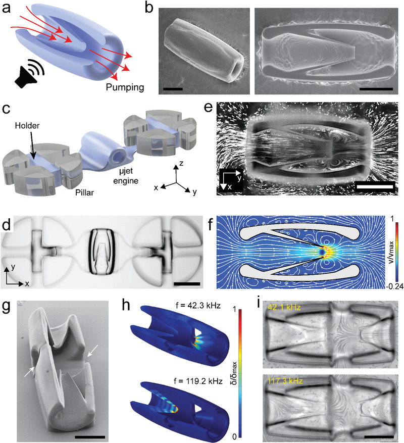
Figure 1.

The fabrication and operation of acoustically excited µjet engines. a) Schematic representation of the working principle of the µjet engine. The red arrows show the direction of pumping generated by acoustic streaming inside the device. b) Electron microscopy images showing fully (left) and partially (right) printed µjet engines. c) Illustration of the microfluidic test platform. The holder was printed along with the µjet engine to stabilize the motion. d) Representative bright‐field image of a 3D‐printed µjet engine that is anchored to pillars. e,f) Streamlines inside and around the µjet engine are visualized experimentally using fluorescent microparticles (e) and numerically using CFD simulations (f), respectively. The localized microstreaming around the tip of the conical wedge results in jet in the middle of the device. g) Electron microscopy image of the bidirectional µjet engine. The arrows show the outlets of the pump. h) Numerical simulations show addressable acoustic excitation of the µjet engine within the same device at different frequencies. Figure S5 in the Supporting Information shows corresponding images with exaggerated deformation. i) Streamlines showing the flow generated at the resonance frequency of each µjet engine. Scale bars: 75 µm in (b), (e), and (i) and 150 µm in (d).
