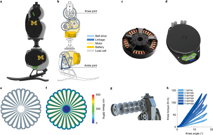
Fig. 1. The OSL and its design components.
a, Rendering of the OSL. b, Schematic of the OSL, highlighting the transmission, electronics and load cell. c, Output view of the electric motor used in the OSL. d, Output view of the motor integrated with the open-source motor controller and embedded system. e, Side view of a single spring disk. f, Finite element analysis of a spring disk being deflected by the gear-shaped internal shaft. The colours represent the von Mises stress. g, Exploded view of six springs stacked inside the knee output pulley. h, Torque-angle relationship of the knee with 1–6 springs stacked inside. Each spring has a stiffness of approximately 100 N m rad−1. We tested each condition five times.

