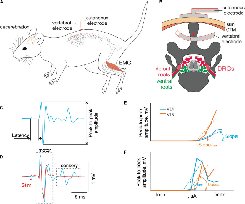
FIGURE 1.
(A) Design of the experiment. The decerebrate rat is fixed in the custom stereotaxic frame and the holes were drilled in the spinous processes of the VT12–VS1 (red dots) vertebrae. The stimulating vertebral electrode was placed alternately in the hole in each vertebra. The stimulating cutaneous electrode was placed in the zones between adjacent vertebrae. The intramuscular electrodes were implanted to record EMG signals. (B) The representative scheme of the frontal section of vertebra VL2 with the spinal cord, dorsal (red) and ventral (green) roots, and dorsal root ganglia (DRGs, pink) inside the vertebral canal. The position of the stimulating cutaneous electrode and vertebral electrode in the spinous process is shown. The contact insulation-free area of the vertebral electrode indicated with a red arrow. (C) An example of motor-evoked potential with the main characteristics measured. (D) An example of motor-evoked potential to first (blue) and second (red) pulse of double-pulse stimulation. (E,F) The recruitment curves of motor (E) and sensory (F) responses at stimulation of different vertebrae and their slopes (max, maximal slope; i, slope at stimulation of some other vertebra).

