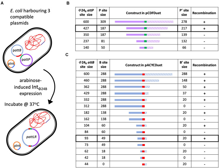
FIGURE 3.
Determining the minimal attP and attB sites utilized by IntΦ24B. (A) Diagram depicting the in situ assay setup, the arabinose induction of IntΦ24B expression, and the resulting chimeric plasmid. (B) The design of the various attP constructs (plasmids with nomenclature pΦ24B-attP, Supplementary Table 1), providing information on the lengths of the P (solid purple) and P’ (hashed purple) sequences and drawn to scale as they flank the 24 bp central crossover site (green). The detection of recombination (+) or absence (–) is also indicated. (C) The design of the various attB constructs (plasmids with nomenclature pΦ24B-attB, Supplementary Table 1), providing information on the lengths of the B (solid blue) and B’ (hashed blue) sequences and drawn to scale as they flank the 24-bp central crossover site (red). The detection of recombination (+) or absence (–) is also indicated.

