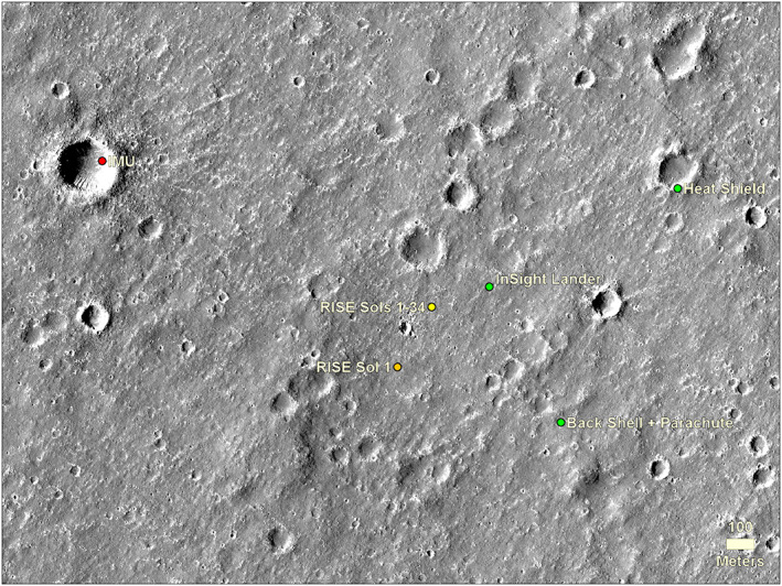
Figure 5.

Area around the lander in HiRISE image showing the location of the lander, heatshield, and backshell (and parachute) and estimated positions from the IMU within the first few days after landing and RISE after the first day and after 34 sols of tracking with an improved rotation model (Golombek, Warner, et al., 2020). HiRISE image ESP_036761_1845, which is one of the stereo pairs used for the HiRISE DEM of this area. North is up.
