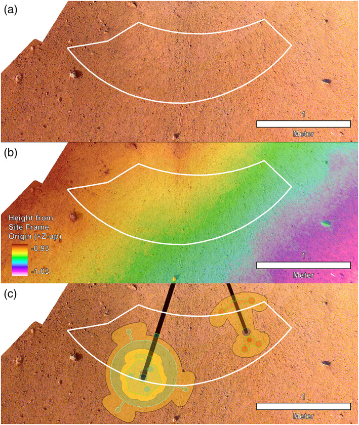
Figure 7.

Image mosaic, DEM, and instrument placements selected by the ISSWG and project. (a) The first IDC image mosaic created of the workspace at 1 mm/pixel with the deployment area outlined in white. (b) High‐resolution DEM produced from the second mosaic of the workspace at 2 mm per elevation posting and the deployment area outlined in white. Note that the deployment area has a total relief measured in centimeters. Elevations are reported in negative site frame Z coordinates, because site frame has Z positive coordinates down, which is opposite of a normal topographic map. (c) Locations selected for the instruments with black lines to the instrument grapple points. SEIS and WTS are to the left and HP3 is to the right. North is up for all.
