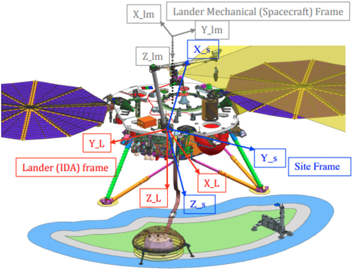
Figure 8.

Spacecraft coordinate frames and the deployment space. The lander mechanical (spacecraft) frame (also referred to as the spacecraft mechanical, SM frame in the text) is shown in gray with the origin at the launch vehicle interface about 1 m above the center of the spacecraft deck and the axes marked lm. The lander (IDA) frame and the Site frame have their origins at the base of the shoulder joint of the arm (IDA) on the lander deck. The Lander frame (also referred to as the IDA frame in the text) is in red with the axes marked L. The site frame (referred to as SF in the text) has Z down along the gravity vector and is shown in blue with the axes marked s. The deployment space is to the south of the lander and the solar panels are roughly east and west. Note the two RISE antennas (green cones) and the TWINS masts on the edge of the deck in the +Y and −Y directions of the SM frame. The spacecraft deck is shown in more detail in Figure 10.
