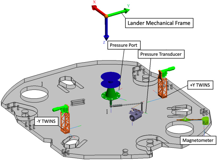
Figure 10.

Diagram of the lander deck from above showing the pressure sensor and port, the magnetometer, and the −Y and +Y TWINS masts in the lander mechanical frame. The lander mechanical frame origin shown (color arrows) is about 1 m above the lander deck. The location of the RISE antennas are near the TWINS booms (see Figures 8 and 12).
