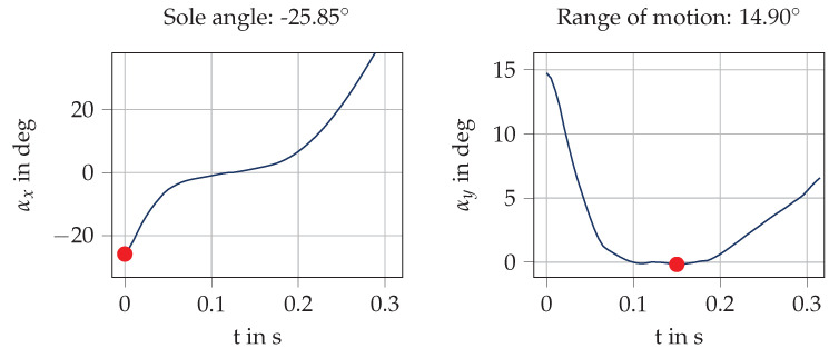
Figure 7.
Visualization of angle computation for a sample stride from the cavity sensor. The angles are depicted from ( s) to ( s). The sole angle is defined as the rotation in the sagittal plane between IC and MS. As the orientation is initialized with zero at MS, the sole angle is the angle at . The range of motion is defined as the difference between the maximum and minimum (red dots) of the angle in the frontal plane during ground contact.

