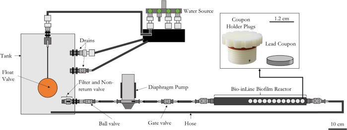
Fig. 8. Schematic representation of the drinking water biofilm reactor (DWBR).
The system is composed by a tank of 25 L connected to a source of local tap water, a float valve which controls the entrance of water to the tank, a diaphragm pump to create a constant flow (5.3 L/min), and one Bio-inline bioreactor with 12 lead coupons. Ball valves and gate valves were added to control the flow through the system, and two drains (one principal and one for emergency), were installed to renew the water inside the tank twice per day (flow of 35 mL/min). The scale is indicated as a line in the lower right corner of the figure, corresponding with 10 cm.

