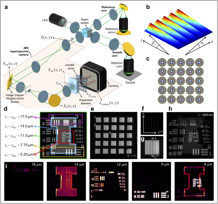
Fig. 1.
(a) Schematic representation of Snapshot OCM using an LED as light source and an IMS-based hyperspectral camera as a detector. The areas shaded orange denote the camera. The optical path lengths of the sample and the reference arms are assumed to be nearly equal. (b) The image mapper simulated as a pure phase function. The surface plot of the phase is shown here after unwrapping along . Note that the angles and are usually very similar; however, since the size of each slice along is significantly longer than its size along , the range of phase for the same tilt is significantly larger in than in . Therefore, the tilt of each slice along appears negligible. (c) The phase of the simulated lenslet array. (d) The simulated 3D object where the different features are highlighted with borders of different colors to indicate their axial displacements with respect to the reference arm. (e) The simulated image on the camera after illumination with a broadband light source. Each block represents the image formed after a lenslet, the adjacent numbers indicate the address of the lenslet array. (f) Representative image on the camera for monochromatic illumination from a single lenslet to illustrate the effect of image slicing, the gap between two adjacent slices, and the addressing schema. (g) Representative image on the camera for broadband illumination from a single lenslet to illustrate the effect of the dispersive element in filling the gaps between adjacent slices and the addressing schema that is relevant for reconstruction. (h) reconstructed from the image in (e). (i) Filmstrip of at different depths in the Snapshot OCM volume that has the closest match to the depths in (d). The numbers at the top right corner of each frame indicates its location in .

