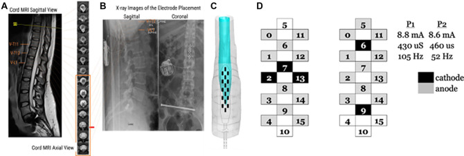
Figure 1.
Site of implantation of the electrode array and stimulating configuration for cardiovascular stability-spinal cord epidural stimulation (CV-scES). (A) Sagittal and Axial MRI sections of the lumbosacral cord were used to calculate the cross-sectional area of the spinal cord and cerebrospinal fluid to create a 3-D reconstruction of the spinal cord at the lumbosacral enlargement. (B) Sagittal x-rays indicating the final placement of the electrode array. (C) 3-D reconstruction of the electrode array relative to the lumbosacral enlargement. (D) Graphical representation of electrode configuration for CV-scES, configuration uses two programs (P1 and P2) running concurrently. Cathodes are represented in black and anodes in gray. Each program runs with an independent stimulating amplitude, pulse width, and frequency.

