

Abstract
To synthesize evenly grafted copolymers, gamma radiation of homogeneous solutions was employed to graft poly(ethylene glycol) methacrylate (PEGMA) onto polyethersulfone (PES). The grafting was verified by Fourier transform infrared spectroscopy, and the degrees of grafting (DGs) were determined by elementary analysis. The PES-g-polyPEGMA copolymers with different DGs were obtained by changing the monomer concentration. Membranes were cast from pristine PES, PES/PEG blends, and PES-g-polyPEGMA with different DGs, respectively, via nonsolvent-induced phase separation. Results from water contact angle measurements and scanning electron microscopy analysis indicated that increasing DGs led to PES-g-polyPEGMA membranes with increasing hydrophilicity and porousness. Filtration experimental results showed that increasing DGs without adding pore-forming agents caused PES-g-polyPEGMA membranes with higher permeability. Compared with PES/PEG membranes with analogous permeation characteristics, in which PEG is added as a pore-forming agent, PES-g-polyPEGMA membranes exhibited superior antifouling properties.
1. Introduction
Polyethersulfone (PES) is a typical membrane material with excellent properties, such as thermal stability and chemical resistance.1,2 However, because of its hydrophobicity, it may be susceptible to fouling, which can significantly reduce the performance of ultrafiltration (UF) membranes, that is, gradual decrease of membrane flux with time and use, which requires extra subsequent treatment.3 Therefore, increasing attention is paid to prevent or reduce interactions between membranes and foulants.
Considerable amount of work has been reported to improve the antifouling performance of PES membranes.4−6 One of the most effective methods is PEGylation,7−9 a process of both covalent and noncovalent attachment or amalgamation of polyethylene glycol (PEG) polymer chains to molecules and macrostructures because PEG, a linear water-soluble polymer, has many positive properties such as hydrophilicity, low toxicity, and excellent biocompatibility.10,11 PEGylated materials have been proved to demonstrate superior low-fouling abilities to resist nonspecific protein adsorption.12−14 Poly(ethylene glycol) methyl methacrylate (PEGMA) is one of the most used PEGylation reagents, and its methacrylate end group can serve as a binding site for the covalent attachment of PEG to PES.15−17
A number of methods have been used for the chemical PEGylation of PES with PEGMA. Susanto and Ulbricht, using photo-initiated graft copolymerization, obtained PES membranes with thin interlayers or graft brushes of polyPEGMA on the surfaces that showed higher adsorptive fouling resistance.18,19 Such PES membranes exhibited a broad spectrum of antifouling properties, as can be seen from the filtration of different substances.20,21 Nevertheless, photografting may change the surface pore structure of the membrane, leading to the degradation of filtration performance and even blocked pores.22,23 To compensate the reduction in water permeability induced by immobilizing PEGMA on the membrane surface, Sharifloo et al. mixed PES with halloysite nanotubes, followed by plasma treatment, and grafted PEGMA on the PES-mixed matrix membrane. A membrane with a highly permeable sublayer and good antifouling performance was fabricated.24 Xia et al. synthesized PEGMA and methacrylic acid (MAA) into a microgel by a one-step cross-linking process and mixed them into the PES membrane. The modified membrane possessed strong resistance capability to the bioadhesion of various organisms.25 Peng et al. synthesized the copolymer of PES-g-PEGMA by using benzoyl peroxide as a chemical initiator in a heterogeneous polymer/monomer reaction system, and PES-g-PEGMA membranes with the addition of PEG demonstrated a stable antibiofouling feature.26 Also, PES-g-PEGMA can be used as a membrane modifier to blend with poly(vinyl chloride) (PVC) to fabricate PVC/PES-g-PEGMA membranes which showed superior antifouling properties.27 Belfer et al. and Roihatin and Susanto applied redox initiators to initiate the radical grafting of PEGMA after the PES membrane preparation and during the membrane formation.28,29 Li et al. tried to graft PEGMA onto the PES membrane surface by surface-initiated atom transfer radical polymerization (ATRP) with a two-step process. The first step was to chloromethylate the aromatic PES, and the second step involved the ATRP of PEGMA using chloromethylated aromatic PES as the macroinitiator.30
Gamma radiation-induced grafting is an effective method for polymer modification owing to its superior penetrability and mild reaction conditions. Because of its ability to form reactive radicals on all practically known polymers, gamma radiation enables one to perform grafting on various polymers. Compared with chemical methods, radiation-induced grafting does not require heating of the system to initiate the graft polymerization reaction; hence, the polymer structure is not changed and temperature-sensitive monomers can be grafted. Furthermore, the whole modification process may not require any initiator to ensure the purity of the product.31−33 Although gamma radiation-induced graft copolymerization has been reported for decades, studies on PEGylation of PES by gamma radiation-induced grafting were rare. Mok claimed that PES UF membranes, after being modified by grafting PEG, showed improved antifouling performance. However, in Mok’s study, PEG was used without the modification of any functional groups.34 In our previous studies, UF membranes were prepared with gamma radiation-induced copolymers of PES grafted by a series of small molecular monomers such as N-vinyl-2-pyrrolidone and MAA. The results showed that the grafting of these small molecular monomers could strongly enhance the hydrophilicity of the membrane, whereas their antifouling property needed to be further improved.35,36
In the present study, to make the grafting more even, PES was grafted with PEGMA by the gamma radiation of a homogeneous solution consisting of a monomer (PEGMA), a polymer (PES), and a solvent [N,N-dimethylacetamide (DMAc)], and then the membranes were cast from PES-g-polyPEGMA copolymers with different degrees of grafting (DGs) without adding pore-forming agents via nonsolvent-induced phase separation (NIPS). The effect of the monomer concentration on the DG was studied based on elementary analysis (EA), and the copolymers were characterized by Fourier transform infrared (FTIR) spectroscopy. The hydrophilicity, morphology, and filtration properties of the membranes were investigated by water contact angle measurements, scanning electron microscopy (SEM) analysis, and UF experiments. The antifouling properties were evaluated by the filtration of bovine serum albumin (BSA) solutions through the membranes and measurement of water flux recoveries after water cleaning. BSA acted as a model foulant in this study.
2. Materials and Methods
2.1. Materials
PES (Mw = 142,000) was purchased from Shandong Caihong Advanced Material Company, China, and dried at 80 °C in a vacuum oven for 24 h before use. DMAc, polyethylene glycols (PEG400), and BSA were purchased from Sinopharm Chemical Reagent Co., Ltd. PEGMA (Mn = 300) was purchased from J&K Scientific Ltd. Water purified with a Milli-Q system from Millipore was used.
2.2. Synthesis of Graft Copolymers
PES powders were first put into a flask filled with DMAc as the solvent and stirred for 24 h at 60 °C to be completely dissolved. After cooling the PES/DMAc solvent to room temperature, PEGMA was added into the same flask by continuous stirring for another 6 h. The formula is listed in Table 1. Then, the solutions were transferred into glass tubes, bubbled with nitrogen for 20 min in order to remove oxygen, and sealed. These samples were irradiated by gamma rays from a 60Co source at room temperature for a period of time. After radiation, the solutions were slowly poured into hot water to precipitate the graft copolymers (PES-g-polyPEGMA). Finally, the precipitates were dried at 80 °C in a vacuum oven until the weight remained constant.
Table 1. Recipe for the Synthesis of PES-g-polyPEGMA.
| no. | PES/g | PEGMA/g | DMAc/g | total/g |
|---|---|---|---|---|
| 1 | 10 | 1 | 89 | 100 |
| 2 | 10 | 3 | 87 | 100 |
| 3 | 10 | 5 | 85 | 100 |
| 4 | 10 | 7 | 83 | 100 |
| 5 | 10 | 9 | 81 | 100 |
The DG of PES-g-polyPEGMA is defined by eq 1
| 1 |
where W1 is the weight of PES-g-ployPEGMA and W0 is the weight of the pristine PES. However, it was difficult to determine the DG by the weight measurement method. In this study, the DG was determined by EA.36
2.3. Elementary Analysis
The chemical composition of the samples was analyzed by a Vario MICRO Cube elemental analyzer (Elementary company). A 0.5 mg sample was used for testing with the Vario MICRO Cube CHNS pattern. The carbon and sulfur mass fractions of samples were collected for calculation. The DG was calculated by eq 2
| 2 |
where MS is the mass fraction of the sulfur element in the graft copolymers; 32 is the atomic weight of sulfur and 232 is the molecular weight of the PES repeating unit.
2.4. FTIR Characterization
A finely ground mixture of the sample and IR-grade KBr was pressed into a pellet for IR analysis. The FTIR spectra were recorded on a Nicolet Avatar 370 FTIR spectrometer (Thermo Nicolet Instrument Corporation, Wisconsin, USA) in the transmission mode, and 32 scans were accumulated at a resolution of 4 cm–1.
2.5. Contact Angle Measurements
The samples were spin-coated on a glass coverslip to form films. A 5 μL of water was dropped on the film surface, and the contact angles, their average value, and standard deviation were calculated. The contact angle was measured on an Attension Theta System (KSV Instruments Ltd., Finland). When the side projection of the water droplet was digitally recorded, the contact angle was automatically measured by its built-in software. The contact angles were measured at five different positions on each specimen, and their average value and standard deviation were calculated.
2.6. Preparation of Membranes
The membranes were prepared via NIPS as in our previous work.37 Pristine PES (5.7 g), the graft copolymer (5.7 g), and PES added with PEG400 (5.7 g PES, 3.1 g PEG400) were dissolved in DMAc (26.0 g), respectively, at 70 °C with stirring for 24 h and stabilizing for another 12 h to release the bubbles. The solution was cast on a glass plate with a casting knife of 250 μm thickness and evaporated in air for 15 s and then immersed into a coagulation bath of water at 18 °C. The resultant membranes were stored in water for 2 days to remove the residual solvent before testing.
2.7. SEM Analysis
The SEM images of the morphology of membranes were taken on a LEO1530vp scanning electron microscope (Zeiss, Germany). To obtain the cross-sectional images, the membranes were fractured by using liquid nitrogen. A sample was attached to the sample stage and sprayed with gold before testing. The scanning voltage was set at 10 kV, and the current was 10 mA. The collected images were processed with the commercial software Avizo to determine the number of pores per unit area, pore sizes, and pore size distribution. The image area for analysis was 200 × 200 pixels.
2.8. Filtration Experiment
The membrane filtration experiments were performed at ambient temperature on an OSMO Inspector membrane filtration system built by Convergence (Enschede, Netherlands). The membrane was cut into a circle with an area of 35.3 cm2 and mounted on a flat sheet cross-flow membrane cell. Before the test, the membrane was precompacted at an applied pressure of 0.1 MPa and a surface flow velocity of 2 kg/h for 10 min so that a constant water flux was achieved. The flow meter was turned on by the built-in software to record the water flux, F0. The water flux (F0) was calculated according to eq 3
| 3 |
where Q is the volume of the filtered water, A is the area of the membrane, and ΔT is the time of filtration.
The preparation of BSA solution is as follows: NaCl (8 g), Na2HPO4 (1.42 g), KCl (0.2 g), KH2PO4 (0.27 g), and 800 mL of deionized water were added in a volumetric flask. The pH of the solution was adjusted to 7.4 and diluted to 1 L. A 1 g BSA was added to the buffer solution, and the 1 g/L BSA solution was used as the feed solution. The solution before and after filtration was collected, and the BSA concentration in the solution was determined by a UV-1100 visible—ultraviolet spectrophotometer (Ruili Instruments Ltd., Beijing) according to the procedure described in the literature.38
2.9. Antifouling Evaluation
The antifouling property of the membranes was evaluated from two aspects: the recovery ratio of the pure water flux after the filtration of the BSA solution and the repeated contamination and cleaning. After filtering the BSA solution for 30 min, the circulating solution in the cross-flow system was changed to deionized water, and the surface flow velocity was adjusted to 5 kg/h. This process to clean the surface of membranes lasted for 30 min. The second water flux is recorded as the recovery water flux, F1. The flux recovery ratio (FRR) is calculated according to eq 4
| 4 |
where F0 and F1 represent the water flux before and after fouling, respectively.
3. Results and Discussion
3.1. Kinetics of Grafting Copolymerization
To obtain the proper DG, the effects of the monomer concentration have been investigated. Figure 1 shows the effect of the monomer concentration on the DG. It can be seen that when the radiation dose was 10 kGy and the dose rate was 1.67 kGy/h, the DG raised linearly from 7.4 to 12.8%, with the monomer concentration increasing from 1 to 10 wt %. The monomer concentration higher than 10 wt % would lead to a gel solution.
Figure 1.

DGs of PES-g-polyPEGMA at different monomer concentrations (radiation dose = 10 kGy; dose rate = 1.67 kGy/h).
3.2. Chemical Structure of the Graft Copolymers
The FTIR spectra of pristine PES and PES-g-polyPEGMA with different DGs are shown in Figure 2. In these spectra, the peaks at 1578, 1487, and 1407 cm–1 correspond to the stretching vibrations of the benzene rings.36 The peaks located at 1324 and 1300 cm–1 are attributed to the asymmetric stretching vibrations of the sulfone group. Clearly, the peaks at 1720 cm–1 appeared in all the spectra of the graft copolymer, and their intensities increased with the monomer concentration in the grafting solution. This peak corresponds to the characteristic absorption of carbonyls from the PEGMA molecule,39,40 indicating that PEGMA was successfully grafted onto the PES main chain.
Figure 2.

FTIR spectra of the pristine PES and graft copolymer PES-g-polyPEGMA with different DGs.
3.3. Hydrophilicity of the Copolymers
To minimize the effects of the porous structure of filter membranes on the measurement of their hydrophilicity,18 uniform thin films were prepared by the spin-coating solutions of pristine PES and graft copolymers on glass coverslips. Figure 3 shows their contact angles. Obviously, the pristine PES membrane had poor hydrophilicity, with the contact angle of 72°, whereas the contact angles of the modified membrane decreased to 58, 48, and 40° at the DGs of 7.4, 10.1, and 12.8%, respectively. The increase of DG resulted in the decrease of the contact angle, indicating that the hydrophilicity of the modified membrane is significantly improved by the grafted polyPEGMA chains. The hydrophilicity of the membrane surface is generally recognized as beneficial to the antifouling property of the membranes. As hydrophobic foulants are not easy to be adsorbed on the surface of a hydrophilic membrane,41 the PES-g-polyPEGMA membranes with higher hydrophilicity should show better resistance to foulants with hydrophobility, such as organic contaminants and proteins.
Figure 3.

Contact angles of films prepared from pristine PES and PES-g-polyPEGMA copolymers with different DGs.
3.4. Morphology of Membranes
Figure 4 shows the surface and cross-sectional structures of membranes, and Figure 5 shows the corresponding pore size distribution calculated by Avizo. It was observed from Figure 4 that all the membrane surfaces had a fine pore structure within nanometer scale. In Figure 5, with the increase of the DG, the number of pores per unit area on the surface of the membranes increased, but the pore size did not change visibly, which may result in improved permeability. The typical asymmetric structure can be observed in the cross-sectional images of all membranes, with a thin dense upper layer and a much thicker porous sublayer. The sublayers of PES and graft copolymer membranes were each composed of two types of macropores, finger-like and irregular porous walls with fine sponge-like micropores.37 The increase of the DG was accompanied by the increase of the number of finger-like pores and the size of irregular pores. These results indicated that higher DGs would lead to a more porous structure. The effect of grafting on the formation of porous membranes could be explained from the perspectives of thermodynamics, dynamics, and polymer aggregate dimensions. First, increasing the DG would enhance the thermodynamic instability of the cast solution consisting of polyPEGMA and DMAc, as the graft chain, polyPEGMA, existing in the copolymer, is not miscible with PES. Second, compared with hydrophobic PES, the hydrophilicity of polyPEGMA increases the interaction between the copolymer and the nonsolvent water, which would accelerate the exchange rate between the solvent DMAc and the nonsolvent water. Third, a higher DG would lead to a larger polymer aggregate size in the cast solution. All the above three factors, that is, enhancing the thermodynamic instability of the cast solution, accelerating the exchange rate between the solvent and the nonsolvent, and enlarging the polymer aggregate size in the cast solution, are conducive to the formation of a more porous structure. In other words, increasing the DG would lead to the PES-g-polyPEGMA membrane with a more porous structure.
Figure 4.

SEM images of the surface (left) and cross-sectional (right) morphology of the membranes: (a) pristine PES membrane, (b) PES-g-polyPEGMA with DG of 7.4%, (c) PES-g-polyPEGMA with DG of 10.1%, and (d) PES-g-polyPEGMA with DG of 12.8%.
Figure 5.

Surface SEM images of pore size distribution.
3.5. Filtration Performances of Membranes
To study the effect of grafting on the membrane filtration performance, membranes of PES, PES/PEG, and PES-g-polyPEGMA were prepared. Figure 6a,b displays the results of UF experiments performed with pure water and BSA aqueous solutions. It can be found that the rejection for all the membranes were more than 90%. For the PES membrane without the addition of pore-forming agents, both the water flux and the BSA flux were extremely low. Compared with the PES membrane, PES-g-polyPEGMA membranes without the addition of pore-forming agents exhibit better permeability. Both the water flux and the BSA flux increased as the DG increased, with the latter smaller than the former. In this study, with the increase of the DG from 7.4 to 10.1 and 12.8%, the water flux raised from 20.0 to 57.0 and 163.3 L m–2 h–1, and the BSA flux from 9.3 to 25.0 and 72.3 L m–2 h–1, respectively, indicating that grafting PEGMA without adding any pore-forming agent improved membrane permeability. This case was different from that reported in the literature,26,42,43 in which PES-g-polyPEGMA membranes were prepared with the addition of the pore-forming agent PEG. In this study, the effect of grafting was similar to the case of PES/PEG blend membranes, in which increasing PEG concentration led to higher membrane permeability.44 In this study, a PES/PEG blend membrane, in which 10% of PEG was added as the pore-forming agent was prepared. Its water and BSA fluxes were 42.7 and 24.6 L m–2 h–1, respectively, similar but slightly lower than those (57.0 and 25.0 L m–2 h–1) of the PES-g-polyPEGMA membrane with the DG of 10.1%. The selection of PEG content was based on the following considerations. Among the PES-g-polyPEGMA membranes with different DGs, the membrane with the DG of 10.1% showed better performances, that is, relatively high permeability and mechanical strength, which are suitable for the following antifouling study. When the DG was lower, the permeability was low, and the higher DG, for example −12.8%, led to a membrane with a low mechanical strength. In addition, it is generally accepted that the smaller pore size causes a lower fouling tendency and the larger pore size yields a higher fouling tendency.18 In order to prove that the better antifouling performance was attributed to the grafting of PEGMA rather than the smaller pore size of the membrane, a PES membrane blended with PEG of 10% and a PES membrane grafted by PEGMA with the DG of 10.1% were selected.
Figure 6.

Filtration of the membranes: (a) water flux of pristine PES and PES-g-polyPEGMA membranes with different DGs, (b) BSA flux and BSA rejection ratio of the pristine PES and PES-g-polyPEGMA membranes.
3.6. Antifouling Evaluation
The antifouling performance of the membranes was studied by three cycles of filtration of pure water, filtration of BSA solution, and cleaning by deionized water. The FRR was used to identify the extent of antifouling. In the present study, a cross-flow mode of the filtration system was adopted, which allowed in situ measurements and online cleaning of the membrane by changing the type of fluid (water or BSA solution) and its flow velocity. The conventional dead-end stirring filtration system was not able to do so.45−47 By using the filtration system in the present study, the flux before and after cleaning can be measured repeatedly.
Figure 7a shows the fluxes of both pure water and BSA solution in the three filtration cycles, and Figure 7b is the corresponding FRR. It was observed that the BSA flux invariably dropped rapidly compared with the water flux in each cycle, and the water flux in the following cycle recovered significantly after the online cleaning. This reversible flux decline may be ascribed to concentration polarization. The FRRs of the PES/PEG membrane after each of the three cycles were 73.8, 65.2, and 63.4%, showing a downward trend, whereas the FRRs of the PES-g-polyPEGMA membrane were 90.0, 90.9, and 90.3%, practically unchanged. This means that except the water flux after the first cleaning, which had not recovered to 100% (the FRR was 90%), the subsequent water fluxes (after the second cleaning) were fully recovered. The irreversible flux decline after the first cleaning may be caused by pore blocking. The continuous drop for the PES/PEG membrane versus little change for the PES-g-polyPEGMA membrane in the water flux after the second cleaning could be explained as follows: in the former case, it was caused by adsorptive fouling, and in the latter case, because of the pronounced improvement of adsorptive fouling resistance caused by the grafted polyPEGMA, water fluxes were fully recovered. It can be concluded that PES-g-polyPEGMA membranes possess superior antifouling properties. The antifouling experiments were repeated for PES-g-polyPEGMA membranes with the DG of 7.4% and 12.8%. The same conclusion, that is, grafting PEGMA could improve the antifouling property, was reached. However, low DG led to low permeability and high DG led to low strength.
Figure 7.

Antifouling evaluation of the membranes: (a) Flux of multiple cycle contamination and cleaning of PES/PEG and PES-g-polyPEGMA membranes. (b) FRRs under multiple cycles of PES/PEG and PES-g-polyPEGMA membranes.
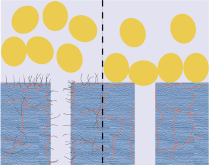
Figure 8 shows that the antifouling mechanism of the PES-g-polyPEGMA membrane is better than that of the PES/PEG membrane. The antifouling performance of membranes mainly depends on the existence and content of PEG in the membranes. It has been reported that PEG segments, with good hydrophilicity, can bind numerous water molecules through hydrogen bonding to form a “hydration layer” which acts as a barrier for protein adsorption on the surface.48 Moreover, PEG segments have a large steric hindrance effect because of the good flexibility and mobility of the C–O–C bond in the PEG chains, bringing about excellent impedance on protein adsorption.49,50 In the PES-g-polyPEGMA membranes, the PEG segments were covalently attached on the PES main chains, retarding the accumulation of protein molecules on the surface of grafted membranes, as shown in Figure 8a. However, the majority of the free PEG molecules will leach out in preparing PES/PEG membranes when they are added as the pore-forming agents. Hence, the PES/PEG membrane is more hydrophobic, and the PEG molecules with less residues on the membrane surface cannot take effect as well as their counterpart (i.e., PEG segments in the grafted membrane). In this case, more and more protein accumulated on the surface of the membrane with time, as shown in Figure 8b.
Figure 8.

Schematic diagram of the antifouling mechanism of (a) PES-g-polyPEGMA membrane and (b) PES membrane.
4. Conclusions
In this study, PEGMA was grafted onto PES by the gamma radiation of a homogeneous solution consisting of a monomer, a polymer, and a solvent. The study of the grafting copolymerization kinetics indicated that the DG increased with the monomer concentration The grafting improved the hydrophilicity of PES.
Membranes of PES, PES/PEG, and PES-g-polyPEGMA were prepared via NIPS. The morphology study proved that compared with pristine PES, grafting PEGMA would lead to more porous membranes. The results from the UF experiment with in situ measurement and online cleaning showed that both blending PEG with PES and grafting PEGMA onto PES would enhance the permeability of membranes. However, compared with PES/PEG membranes, PES-g-polyPEGMA membranes possess excellent antifouling properties.
Acknowledgments
The help of Dr. Yanling Xue in SEM image analysis is appreciated. This work was financially supported by the National Natural Foundation of China (NSFC, nos. 11375252, U1632135 and 11975297).
Author Contributions
Z. Hou proposed the idea of grafting PEGMA on PES by a homogeneous solution radiation. Z. Hou and H. Yang designed the experiments and provided necessary resources. D. Lou performed the experiment and analyzed the data. D. Lou, H. Yang, and Z. Hou co-wrote the paper. Y. Liu provided guidance on the experiment. T. Wang provided experimental assistance. All authors discussed the results and commented on the manuscript.
The authors declare no competing financial interest.
References
- Zhao C.; Xue J.; Ran F.; Sun S. Modification of polyethersulfone membranes – A review of methods. Prog. Mater. Sci. 2013, 58, 76–150. 10.1016/j.pmatsci.2012.07.002. [DOI] [Google Scholar]
- Barth C.; Gonçalves M. C.; Pires A. T. N.; Roeder J.; Wolf B. A. Asymmetric polysulfone and polyethersulfone membranes: effects of thermodynamic conditions during formation on their performance. J. Membr. Sci. 2000, 169, 287–299. 10.1016/s0376-7388(99)00344-0. [DOI] [Google Scholar]
- Koehler J. A.; Ulbricht M.; Belfort G. Intermolecular Forces between Proteins and Polymer Films with Relevance to Filtration. Langmuir 1997, 13, 4162–4171. 10.1021/la970010m. [DOI] [Google Scholar]
- Hoseinpour V.; Ghaee A.; Vatanpour V.; Ghaemi N. Surface modification of PES membrane via aminolysis and immobilization of carboxymethylcellulose and sulphated carboxymethylcellulose for hemodialysis. Carbohydr. Polym. 2018, 188, 37–47. 10.1016/j.carbpol.2018.01.106. [DOI] [PubMed] [Google Scholar]
- Kull K. R.; Steen M. L.; Fisher E. R. Surface modification with nitrogen-containing plasmas to produce hydrophilic, low-fouling membranes. J. Membr. Sci. 2005, 246, 203–215. 10.1016/j.memsci.2004.08.019. [DOI] [Google Scholar]
- Shi X.; Tal G.; Hankins N. P.; Gitis V. Fouling and cleaning of ultrafiltration membranes: A review. J. Water Process Eng. 2014, 1, 121–138. 10.1016/j.jwpe.2014.04.003. [DOI] [Google Scholar]
- Tripathi B. P.; Dubey N. C.; Stamm M. Polyethylene glycol cross-linked sulfonated polyethersulfone based filtration membranes with improved antifouling tendency. J. Membr. Sci. 2014, 453, 263–274. 10.1016/j.memsci.2013.11.007. [DOI] [Google Scholar]
- Fan X.; Su Y.; Zhao X.; Li Y.; Zhang R.; Ma T.; Liu Y.; Jiang Z. Manipulating the segregation behavior of polyethylene glycol by hydrogen bonding interaction to endow ultrafiltration membranes with enhanced antifouling performance. J. Membr. Sci. 2016, 499, 56–64. 10.1016/j.memsci.2015.10.026. [DOI] [Google Scholar]
- Zhu L.-P.; Xu Y.-Y.; Wei X.-Z.; Zhu B.-K. Hydrophilic modification of poly(phthalazine ether sulfone ketone) ultrafiltration membranes by the surface immobilization of poly(ethylene glycol) acrylates. Desalination 2009, 242, 96–109. 10.1016/j.desal.2008.03.034. [DOI] [Google Scholar]
- Deible C. R.; Petrosko P.; Johnson P. C.; Beckman E. J.; Russell A. J.; Wagner W. R. Molecular barriers to biomaterial thrombosis by modification of surface proteins with polyethylene glycol. Biomaterials 1998, 19, 1885–1893. 10.1016/s0142-9612(98)00098-2. [DOI] [PubMed] [Google Scholar]
- Xu Z.-K.; Nie F.-Q.; Qu C.; Wan L.-S.; Wu J.; Yao K. Tethering poly(ethylene glycol)s to improve the surface biocompatibility of poly(acrylonitrile-co-maleic acid) asymmetric membranes. Biomaterials 2005, 26, 589–598. 10.1016/j.biomaterials.2004.03.008. [DOI] [PubMed] [Google Scholar]
- Harris L. G.; Tosatti S.; Wieland M.; Textor M.; Richards R. G. Staphylococcus aureus adhesion to titanium oxide surfaces coated with non-functionalized and peptide-functionalized poly(L-lysine)-grafted-poly(ethylene glycol) copolymers. Biomaterials 2004, 25, 4135–4148. 10.1016/j.biomaterials.2003.11.033. [DOI] [PubMed] [Google Scholar]
- Hucknall A.; Rangarajan S.; Chilkoti A. In Pursuit of Zero: Polymer Brushes that Resist the Adsorption of Proteins. Adv. Mater. 2009, 21, 2441–2446. 10.1002/adma.200900383. [DOI] [Google Scholar]
- Su Y.-L.; Cheng W.; Li C.; Jiang Z. Preparation of antifouling ultrafiltration membranes with poly(ethylene glycol)-graft-polyacrylonitrile copolymers. J. Membr. Sci. 2009, 329, 246–252. 10.1016/j.memsci.2009.01.002. [DOI] [Google Scholar]
- Tugulu S.; Klok H.-A. Stability and nonfouling properties of poly(poly(ethylene glycol) methacrylate) brushes under cell culture conditions. Biomacromolecules 2008, 9, 906–912. 10.1021/bm701293g. [DOI] [PubMed] [Google Scholar]
- Ye Y.; Huang J.; Wang X. Fabrication of a Self-Cleaning Surface via the Thermosensitive Copolymer Brush of P(NIPAAm-PEGMA). ACS Appl. Mater. Interfaces 2015, 7, 22128–22136. 10.1021/acsami.5b07336. [DOI] [PubMed] [Google Scholar]
- Peeva P. D.; Million N.; Ulbricht M. Factors affecting the sieving behavior of anti-fouling thin-layer cross-linked hydrogel polyethersulfone composite ultrafiltration membranes. J. Membr. Sci. 2012, 390–391, 99–112. 10.1016/j.memsci.2011.11.025. [DOI] [Google Scholar]
- Susanto H.; Ulbricht M. Photografted thin polymer hydrogel layers on PES ultrafiltration membranes: characterization, stability, and influence on separation performance. Langmuir 2007, 23, 7818–7830. 10.1021/la700579x. [DOI] [PubMed] [Google Scholar]
- Susanto H.; Ulbricht M. High-performance thin-layer hydrogel composite membranes for ultrafiltration of natural organic matter. Water Res. 2008, 42, 2827–2835. 10.1016/j.watres.2008.02.017. [DOI] [PubMed] [Google Scholar]
- Susanto H.; Roihatin A.; Aryanti N.; Anggoro D. D.; Ulbricht M. Effect of membrane hydrophilization on ultrafiltration performance for biomolecules separation. Mater. Sci. Eng. C 2012, 32, 1759–1766. 10.1016/j.msec.2012.04.036. [DOI] [PubMed] [Google Scholar]
- Saha N. K.; Balakrishnan M.; Ulbricht M. Fouling control in sugarcane juice ultrafiltration with surface modified polysulfone and polyethersulfone membranes. Desalination 2009, 249, 1124–1131. 10.1016/j.desal.2009.05.013. [DOI] [Google Scholar]
- Susanto H.; Balakrishnan M.; Ulbricht M. Via surface functionalization by photograft copolymerization to low-fouling polyethersulfone-based ultrafiltration membranes. J. Membr. Sci. 2007, 288, 157–167. 10.1016/j.memsci.2006.11.013. [DOI] [Google Scholar]
- Susanto H.; Arafat H.; Janssen E. M. L.; Ulbricht M. Ultrafiltration of polysaccharide–protein mixtures: Elucidation of fouling mechanisms and fouling control by membrane surface modification. Sep. Purif. Technol. 2008, 63, 558–565. 10.1016/j.seppur.2008.06.017. [DOI] [Google Scholar]
- Sharifloo M. M.; Ghaee A.; Salimi E.; Sadatnia B.; Mansourpour Z. Hemocompatibility and antifouling properties of PEGMA grafted Polyethersulfone/aminated halloysite nanotubes mixed matrix membrane. Int. J. Polym. Mater. Polym. Biomater. 2018, 68, 762–771. 10.1080/00914037.2018.1493688. [DOI] [Google Scholar]
- Xia Y.; Cheng C.; Wang R.; He C.; Ma L.; Zhao C. Construction of microgels embedded robust ultrafiltration membranes for highly effective bioadhesion resistance. Colloids Surf. B Biointerfaces 2016, 139, 199–210. 10.1016/j.colsurfb.2015.12.018. [DOI] [PubMed] [Google Scholar]
- Peng J.; Su Y.; Shi Q.; Chen W.; Jiang Z. Protein fouling resistant membrane prepared by amphiphilic pegylated polyethersulfone. Bioresour. Technol. 2011, 102, 2289–2295. 10.1016/j.biortech.2010.10.045. [DOI] [PubMed] [Google Scholar]
- Jiang S.; Wang J.; Wu J.; Chen Y.. Poly(vinyl chloride) and poly(ether sulfone)-g-poly(ether glycol) methyl ether methacrylate blend membranes with improved ultrafiltration performance and fouling resistance. J. Appl. Polym. Sci. 2015, 132. 10.1002/app.41726 [DOI]
- Belfer S.; Fainchtain R.; Purinson Y.; Kedem O. Surface characterization by FTIR-ATR spectroscopy of polyethersulfone membranes-unmodified, modified and protein fouled. J. Membr. Sci. 2000, 172, 113–124. 10.1016/s0376-7388(00)00316-1. [DOI] [Google Scholar]
- Roihatin A.; Susanto H. Preparation of Low fouling Polyethersulfone Membranes by Simultaneously Phase Separation and Redox Polymerization. IOP Conf. Ser.: Mater. Sci. Eng. 2017, 202, 012004. 10.1088/1757-899x/202/1/012004. [DOI] [Google Scholar]
- Li L.; Yan G.; Wu J.; Yu X.; Guo Q. Surface-initiated atom-transfer radical polymerization from polyethersulfone membranes and their use in antifouling. E-Polymers 2009, 026, 1618–7229. 10.1515/epoly.2009.9.1.303. [DOI] [Google Scholar]
- Kabanov V. Y.; Kudryavtsev V. N. Modification of Polymers by Radiation Graft Polymerization (State of the Art and Trends). High Energy Chem. 2003, 37, 1–5. 10.1023/a:1021919224451. [DOI] [Google Scholar]
- Shen L.; Feng S.; Li J.; Chen J.; Li F.; Lin H.; Yu G. Surface modification of polyvinylidene fluoride (PVDF) membrane via radiation grafting: novel mechanisms underlying the interesting enhanced membrane performance. Sci. Rep. 2017, 7, 2721. 10.1038/s41598-017-02605-3. [DOI] [PMC free article] [PubMed] [Google Scholar]
- Shim J. K.; Na H. S.; Lee Y. M.; Huh H.; Nho Y. C. Surface modification of polypropylene membranes by -ray induced graft copolymerization and their solute permeation characteristics. J. Membr. Sci. 2001, 190, 215–226. 10.1016/s0376-7388(01)00445-8. [DOI] [Google Scholar]
- Mok S.; Worsfold D. J.; Fouda A.; Matsuura T. Surface Modification of Polyethersulfone Hollow-Fiber Membranes by y-Ray Irradiation. J. Appl. Polym. Sci. 1994, 51, 193–199. 10.1002/app.1994.070510120. [DOI] [Google Scholar]
- Fan K.; Huang J.; Yang H.; Lu R.; Sun X.; Hu J.; Hou Z. pH and thermal-dependent ultrafiltration membranes prepared from poly (methacrylic acid) grafted onto polyethersulfone synthesized by simultaneous irradiation in homogenous phase. J. Membr. Sci. 2017, 543, 335–341. 10.1016/j.memsci.2017.08.063. [DOI] [Google Scholar]
- Huang J.; Yang H.; Chen M.; Ji T.; Hou Z.; Wu M. An infrared spectroscopy study of PES PVP blend and PES-g-PVP copolymer. Polym. Test. 2017, 59, 212–219. 10.1016/j.polymertesting.2017.02.005. [DOI] [Google Scholar]
- Zhou C.; Hou Z.; Lu X.; Liu Z.; Bian X.; Shi L.; Li L. Effect of Polyethersulfone Molecular Weight on Structure and Performance of Ultrafiltration Membranes. Ind. Eng. Chem. Res. 2010, 49, 9988–9997. 10.1021/ie100199h. [DOI] [Google Scholar]
- Noble J. E.; Bailey M. J. A.. Quantitation of Protein. Guide to Protein Purification, 2nd ed.; Elsevier, 2009; Chapter 8, Vol. 463, pp 73–95. [DOI] [PubMed] [Google Scholar]
- Belfer S.; Purinson Y.; Fainshtein R.; Radchenko Y.; Kedem O. Surface modification of commercial composite polyamide reverse osmosis membranes. J. Membr. Sci. 1998, 139, 175–181. 10.1016/s0376-7388(97)00248-2. [DOI] [Google Scholar]
- Wandera D.; Wickramasinghe S. R.; Husson S. M. Modification and characterization of ultrafiltration membranes for treatment of produced water. J. Membr. Sci. 2011, 373, 178–188. 10.1016/j.memsci.2011.03.010. [DOI] [Google Scholar]
- Koehler J. A.; Ulbricht M.; Belfort G. Intermolecular Forces between a Protein and a Hydrophilic Modified Polysulfone Film with Relevance to Filtration. Langmuir 2000, 16, 10419–10427. 10.1021/la000593r. [DOI] [Google Scholar]
- Susanto H.; Ulbricht M. Characteristics, performance and stability of polyethersulfone ultrafiltration membranes prepared by phase separation method using different macromolecular additives. J. Membr. Sci. 2009, 327, 125–135. 10.1016/j.memsci.2008.11.025. [DOI] [Google Scholar]
- Zhao W.; Su Y.; Li C.; Shi Q.; Ning X.; Jiang Z. Fabrication of antifouling polyethersulfone ultrafiltration membranes using Pluronic F127 as both surface modifier and pore-forming agent. J. Membr. Sci. 2008, 318, 405–412. 10.1016/j.memsci.2008.03.013. [DOI] [Google Scholar]
- Shen L.; Li L.; Chen J.; Hong H.; Yu H.; Hou Z.; Lin H.; Lu X. Effects of molecular weight distribution (Md) on the performances of the polyethersulfone (PES) ultrafiltration membranes. J. Membr. Sci. 2015, 490, 220–226. 10.1016/j.memsci.2015.04.068. [DOI] [Google Scholar]
- Becht N. O.; Malik D. J.; Tarleton E. S. Evaluation and comparison of protein ultrafiltration test results: Dead-end stirred cell compared with a cross-flow system. Sep. Purif. Technol. 2008, 62, 228–239. 10.1016/j.seppur.2008.01.030. [DOI] [Google Scholar]
- Shamsuddin N.; Das D. B.; Starov V. M. Filtration of natural organic matter using ultrafiltration membranes for drinking water purposes: Circular cross-flow compared with stirred dead end flow. Chem. Eng. J. 2015, 276, 331–339. 10.1016/j.cej.2015.04.075. [DOI] [Google Scholar]
- Tsibranska I. H.; Tylkowski B. Concentration of ethanolic extracts from Sideritis ssp. L. by nanofiltration: Comparison of dead-end and cross-flow modes. Food Bioprod. Process. 2013, 91, 169–174. 10.1016/j.fbp.2012.09.004. [DOI] [Google Scholar]
- Chen S.; Li L.; Zhao C.; Zheng J. Surface hydration: Principles and applications toward low-fouling/nonfouling biomaterials. Polymer 2010, 51, 5283–5293. 10.1016/j.polymer.2010.08.022. [DOI] [Google Scholar]
- Banerjee I.; Pangule R. C.; Kane R. S. Antifouling coatings: recent developments in the design of surfaces that prevent fouling by proteins, bacteria, and marine organisms. Adv. Mater. 2011, 23, 690–718. 10.1002/adma.201001215. [DOI] [PubMed] [Google Scholar]
- Ostuni E.; Chapman R. G.; Holmlin R. E.; Takayama S.; Whitesides G. M. A Survey of Structure-Property Relationships of Surfaces that Resist the Adsorption of Protein. Langmuir 2001, 17, 5605–5620. 10.1021/la010384m. [DOI] [Google Scholar]