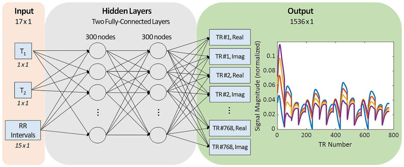
Fig. 7.
Diagram of the proposed neural network architecture. The input to the neural network is a 17-element vector containing a T1 value, a T2 value, and fifteen RR intervals. Next the input passes through two fully-connected layers with 300 neurons per layer. The output has 1536 nodes corresponding to the real and imaginary parts of the signal evolution at 768 time points. Examples of four representative MRF signal evolutions are plotted in the output panel.

