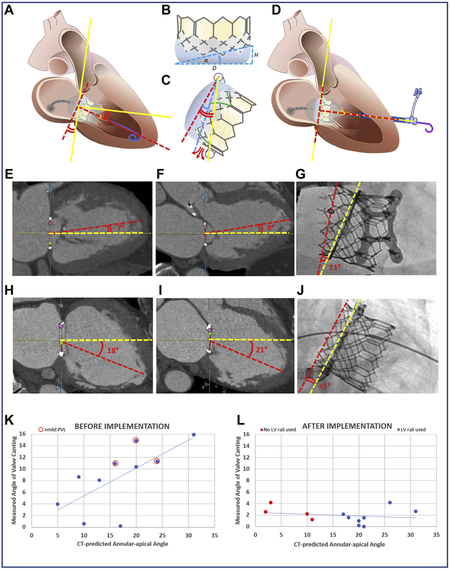
FIGURE 1. The Emory TMVR Angle.

(A) Discordance between mitral annular centerline (yellow lines) and valve orientation imposed by guidewire position within the LV apex (red dashed lines). (B) Valve intrinsic angle α determined by external skirt height. (C) When annular-apical “Emory” angle (red curves) exceeds α (blue curve), annular skirt apposition is not possible, causing PVL (red arrows). (D) The valve is oriented perpendicular to the annual plane using an exteriorized apical guidewire (solid yellow line). Two representative cases demonstrate the canting angle before (E to G) and after (H to J) adopting the new strategy. (E to G) CT-derived Emory angles in (E) bicommissural (medial-lateral) and (F) LV outflow tract (anteroposterior) planes with (G) noncoaxial (canted) deployment evident on fluoroscopy in a case before we adopted selective guidewire exteriorization. (H to J) A case that illustrates improved valve alignment despite large Emory angle α by externalizing the guidewire through a percutaneous para-apical sheath. The graphs show predicted (horizontal-axis) and observed (vertical-axis) valve canting angles before (K) and after (L) adopting the exteriorized LV guidewire strategy for cases when the Emory angle approached 15°. The incidence of >mild PVL (red circles) is reduced. CT = computed tomography; LV = left ventricular; PVL = paravalvular leak; TMVR = transcatheter mitral valve replacement.
