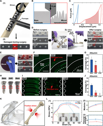
Fig. 4. Mechanical durability of LOIS.

(A) Schematics of (1) mechanical stress applied on the orthopedic implants during surgery and (2) optical image of the damaged orthopedic implant. (B) Schematics of nanomechanical property measurement via nanoindentation on bare surface and LOIS. (C) Nanoindentation force-displacement curves of bare surface and LOIS. (D) Optical images (the damaged areas highlighted with red rectangle) of different types of the orthopedic plates after ex vivo experiment to simulate the mechanical stress–causing damages during surgery. (E) Blood adhesion test and (F) protein adhesion test for the damaged orthopedic plate groups. (G) Measurement of the area coverage of protein adhered on the plates. (H) Optical images of the different types of orthopedic screws after ex vivo experiment. (I) Protein adhesion test to investigate the intactness of the different coatings. (J) Measurement of the area coverage of protein adhered on the screws. (K) Schematics of the rabbit’s movement, inducing fixation stress on fractured bone. (L) (1) Bending test results and optical images before and after bending. Difference of (2) Young’s modulus and (3) flexural strength in bare implant and SHP. Data are presented as means ± SD (*P < 0.05, **P < 0.01, ***P < 0.001, and ****P < 0.0001). Photo credit: Kyomin Chae, Yonsei University.
