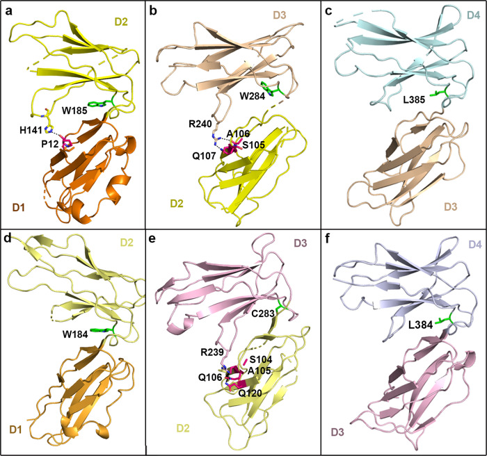
Fig. 5.
Binding modes and the interaction details between adjacent domains in LILRs. All of the structures presented are shown with alignment to superimposed LILRB1 D1. a–c The upper panel indicates the interdomain angles of D1D2, D2D3, and D3D4 in LILRB1. d–f The lower panel indicates the interdomain angles of D1D2, D2D3, and D3D4 in LILRB2. A green stick representation indicates that the residue in the F–G loop is located in the center of the contact region. The residues in the A strand or A–B loop that are responsible for the interaction are shown in hot pink stick representation

