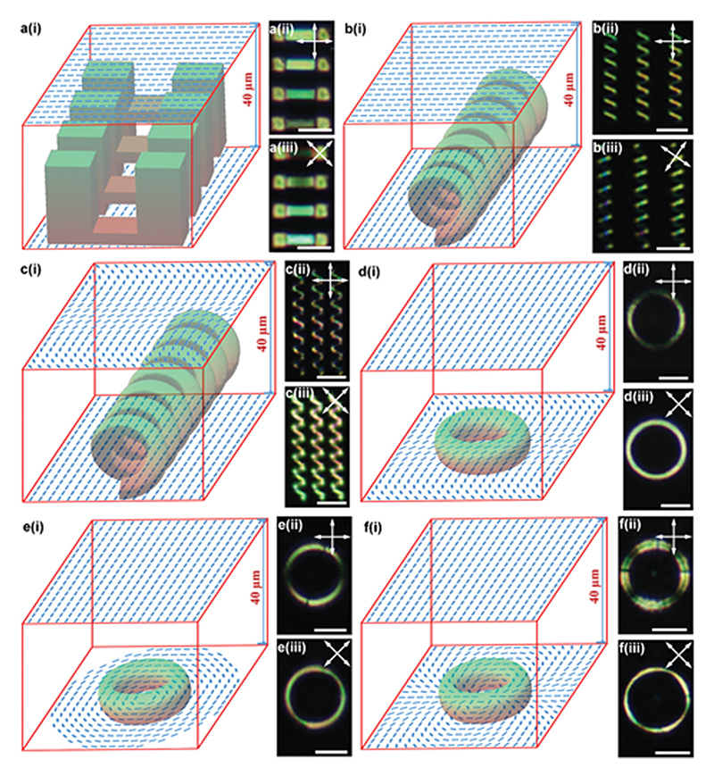
Figure 4. 3D LCN microstructures with encoded 3D director field.
a–f) Suspended films at different heights with twisting molecular alignment (a), coils with twisting molecular alignment (b), coils with a sinusoidal director field on top and uniform molecular alignment on the bottom (c), a ring with uniform alignment on top and sinusoidal pattern on bottom (d), a ring with the uniform molecular alignment on top and +1 defect pattern on bottom (e), and ring with uniform alignment on top and +2 defect pattern on bottom (f); (i), (ii), and (iii) represent the schematic of LC cells and director fields, POM images of LCN structures, and their POM images with rotated polarizers, respectively. Double-sided arrows exhibit the optical axis of the polarizers. All scale bars are 50 µm.

