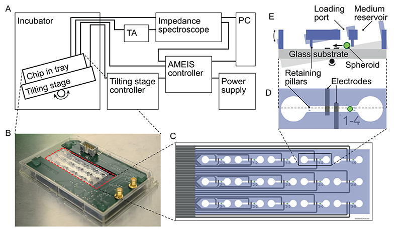
Figure 1. Overview of the AMEIS platform.
(A) schematics of the entire system (TA, transimpedance amplifier); (B) chip (highlighted in dashed red line) and switch board placed in omni-tray; (C) schematic of the chip with 15 separate chambers featuring gray electrodes and blue PDMS structures; (D) close-up of one chamber with reservoirs on the left and right. The spheroid movement in the central channel (580 μm × 700 μm cross section) was confined by retaining pillars on both sides of the channel, and the coplanar EIS electrode set was arranged centrally in the channel; (E) schematic side view showing the medium reservoir and spheroid loading port, as well as the tilting-induced motion of the spheroid over the electrodes.

