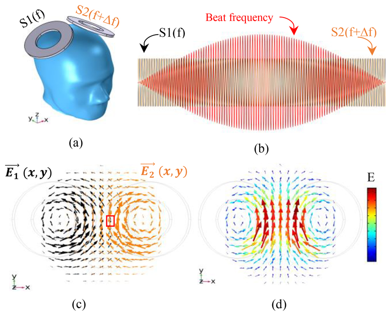
Figure 1.
Concept of the proposed TI-TMS system; (a) Placing two independent stimulation coils on the skull. The stimulus injected into one coil has a frequency of (f) Hz and another has a frequency of (f+ Δf) Hz. (b) The shape of the waves of the injected stimuli (S1 and S2) and their envelope (beat frequency) as a temporal interference effect. (c) E-field vectors caused by S1 and S2 (without interference). An example of where the E-field interference occurs is shown in the red box. (d) The sum of electric field vectors resulting from the interference. (c) and (d) are obtained at the moment when the interference vectors of the two electric fields are at their maximum.

