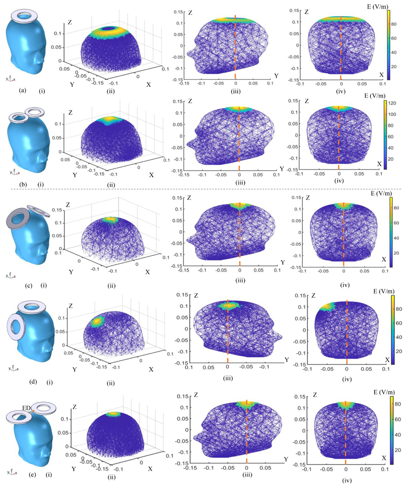
Figure 4.
FEM simulation of electric field distributions of the different coil models and orientations. (a) A Magstim 90 mm single circular coil (P/N 3192). (b) A Magstim 70 mm figure-8 coil (P/N 9925, 3190). (c) - (e) Two Magstim 90 mm single circular coils (P/N 3192) in different orientations with the effect of temporal interference (ED: edge distance). (i) The coil placement on the skull. (ii) Spatial distribution of the induced E-field. (iii) Distribution of the induced E-field on the YZ plane. (iv) Distribution of the induced E-field on the XZ plane. In all simulations, the coil stimulus is a cosine wave with an amplitude of ± 700 volts. For (a) and (b) the stimulus frequency is 2.5 kHz and for the temporal interference simulations the stimulus frequencies are set to 10 kHz and 10.04 kHz. All axes are written in meters.

