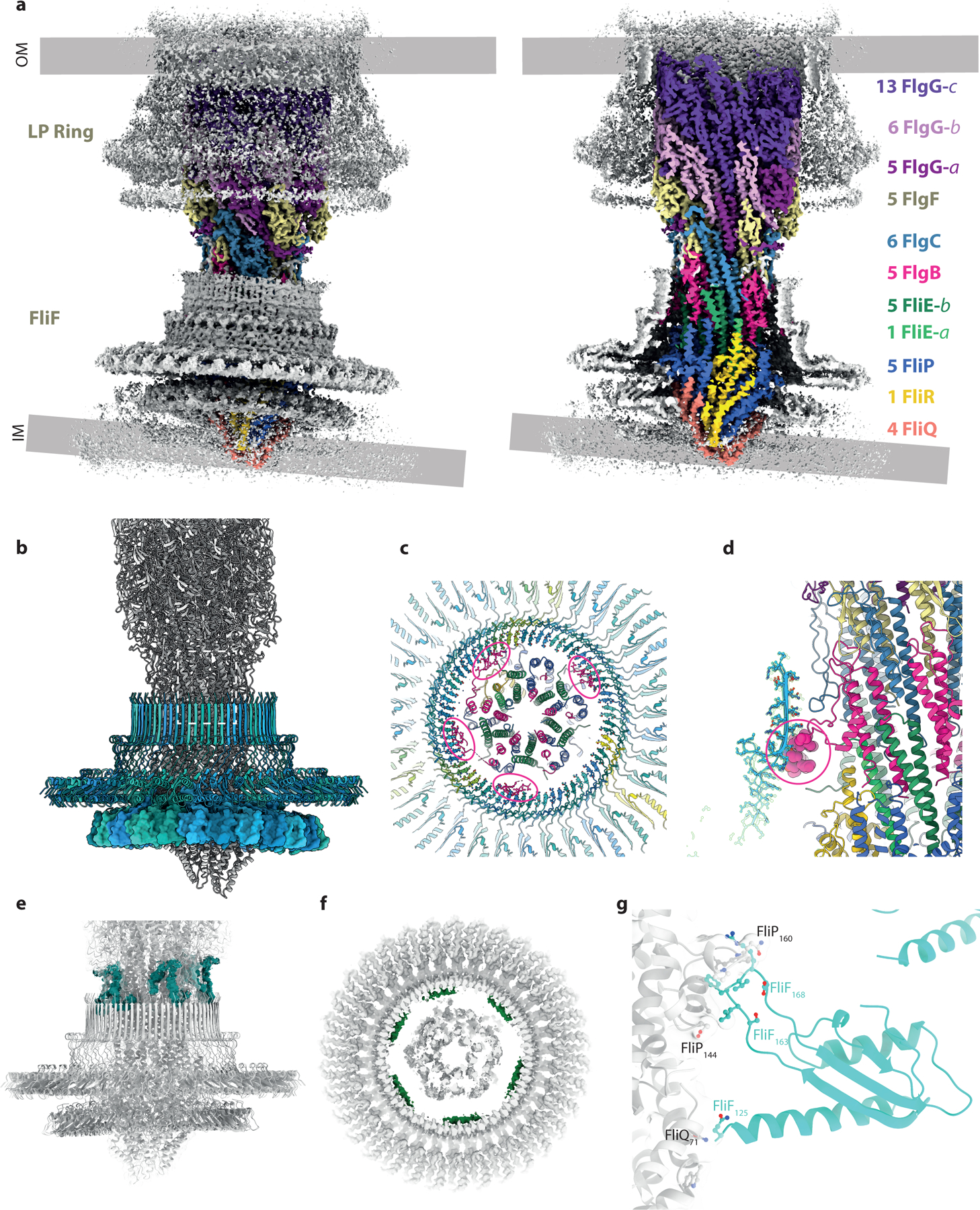
Figure 3. Interactions of the rod and export gate with the OM and IM ring structures.

a, Overview of the C1 volume obtained by focusing alignments on the axial rod components. The volume is colored grey with the exception of the rod components which are colored as in Figure 2(a) on right hand panel shows a cutaway of the left hand panel. The mis-alignment of components in the inner and outer membranes is clear in this view. b, Cartoon of the assembly focusing on the inner membrane components with the 34mer FliF colored in blue shades. The 34-fold RBM3 ring of FliF (blue shade cartoon) is set horizontally revealing the distortion of the 23-mer RBM2 ring (surface representation), presumably driven by contacts between the circular RBM2 oligomer and the helical export gate. Other contacts between FliF and the axial components are shown by coloring the experimental volume according to the putative component contributing the contact. c and d, Interaction between FlgB and the inside of the FliF RBM3/ß-collar. e, Putative FliF loop (teal) reaching around top of FliF assembly to contact axial rod at level of the FlgB/FlgC/FlgF interfaces. f, Putative FliE helix (pink) contacting base of RBM3 ß-collar. g, Close up of contacts between one copy FliF RBM2 and the export gate, coloured as in (b).
