Abstract
This article presents a medical robotic system for deep orbital interventions, with a focus on Optic Nerve Sheath Fenestration (ONSF). ONSF is a currently invasive ophthalmic surgical approach that can reduce potentially blinding elevated hydrostatic intracranial pressure on the optic disc via an incision on the optic nerve. The prototype is a multi-arm system capable of dexterous manipulation and visualization of the optic nerve area, allowing for a minimally invasive approach. Each arm is an independently controlled concentric tube robot collimated by a bespoke guide that is secured on the eye sclera via sutures. In this article, we consider the robot’s end-effector design in order to reach/navigate the optic nerve according to the clinical requirements of ONSF. A prototype of the robot was engineered, and its ability to penetrate the optic nerve was analysed by conducting ex vivo experiments on porcine optic nerves and comparing their stiffness to human ones. The robot was successfully deployed in a custom-made realistic eye phantom. Our simulation studies and experimental results demonstrate that the robot can successfully navigate to the operation site and carry out the intervention.
Index Terms: Surgical robotics, steerable catheters/needles, mechanism design, medical robots and systems
I. Introduction
THE cerebrospinal fluid (CSF) is a clear liquid which maintains the intracranial pressure (ICP) at 10-18 cm H2O.
Disorders such as infection, brain lesions, or idiopathic intracranial hypertension can result in raised ICP, which in turn can cause both generalized and ocular damage, such as compression of the optic nerve around its whole circumference in a “choking” manner. This can cause optic nerve head (ONH) edema (also known as papilledema) [1] with optic disc protrusion and engorgement of blood vessels and nerve fibres. Given the role of the optic nerve as the transmitter of photosensory information from the retina to the brain, papilledema may lead to permanent vision loss.
The primary treatment of elevated ICP is medication. When this fails, alternatives are Ventriculo-Peritoneal Shunting (VPS) and Optic Nerve Sheath Fenestration (ONSF). VPS is a risky complex neurosurgical procedure aiming to redirect excess CSF from the ventricles to the abdominal compartment. ONSF involves surgically opening the optic nerve sheath to locally provide a sustained drop in ICP and relax “choking”. ONSF is a less invasive but still surgically complex option to treat significant papilledema and the elevated hydrostatic pressure on the optic nerve [1].
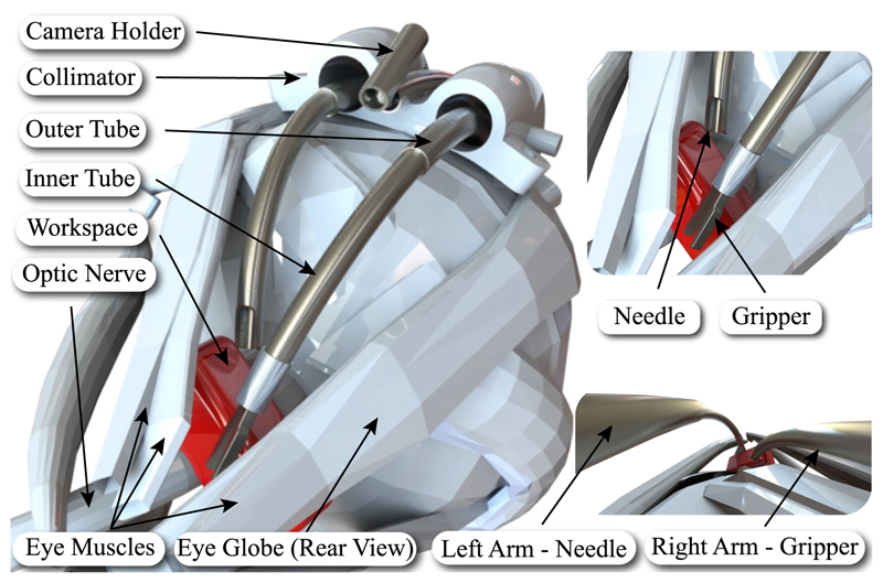
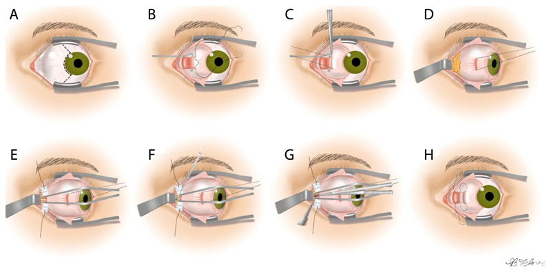
The preferred approach to ONSF, which we aim to robotise (see Fig. 1), is termed “Medial Transconjunctival” [1] (see Fig. 2); it minimizes surgical invasiveness, bleeding, and damage to structures local to the optic nerve [1]. To reach an increased operating field, however, the medial rectus muscle has to be separated from the eye globe, which requires extensive manipulation of the eye. This complicates the intervention and increases the chance of inadvertent tissue damage. Therefore, ONSF is currently reserved for patients with significant papilledema and progressive or impending visual loss [1].
Fig. 1.
Left: Illustration of periocular access to the optic nerve using the developed robot. Right: Visualization of the surgical arms and tools. The red box indicates the desired workspace.
Fig. 2. Medial transconjuctival approach for ONSF.
A: Peritomy is performed, B: Isolation of the medial rectus muscle, C: The muscle is detached from the globe, D: Lateral retraction of the globe, E: The orbital fat is retracted away from the optic nerve, F: Incision of the optic nerve sheath, G: Extension of the incision to a total length of 3 to 5 mm, H: The medial rectus is reattached and the peritomy is closed. Image adapted adapted from [1].
ONSF significantly improves the function of the optic nerve [2], but is not widely used due to the difficulty in surgical access and risk of sight loss [3]. Notably, ONSF complication rate was found to be as high as 45% (mean of 12.9%) [4]. Additionally, [4] highlighted that approximately 1 out of 8 (sample of 317) ONSF interventions fail to restore vision and require re-operation due to sustained elevated ICP. Naturally, re-operation may lead to further complications.
Surgical robots can offer solutions to the unique challenges in deep orbital interventions such as ONSF. Our work builds on background research on continuum robots, and specifically concentric tube robots, to propose a novel approach to access the eye orbit and perform procedures like ONSF. We suggest to access the eye orbit and the optic nerve by navigating peri-ocularly, following the eye surface, to reach the position where multiple concentric tube robot arms collaboratively perform the intervention (see Fig. 1).
Continuum robots have advantages in single-site surgical procedures compared to rigid counterparts as they can follow natural pathways to access positions deep inside the human body [5]. Concentric tube robots (CTRs), a representative continuum robot, can navigate the anatomy without requiring external environmental forces [6], [7]. CTRs comprise precurved super-elastic concentric tubes, which rotate and telescopically translate to control the robot’s shape and the end-effector’s pose. As the tubes can be reduced to hundreds of micrometers in diameter [8], [9], CTRs can be deployed through narrow corridors while retaining force transmission capability and dexterity at their tip. CTRs have been explored for many surgical applications including heart [10], lung [7], brain [11], eye [8], [12], and kidney [13], showing the increasing interest by the research community.
Here, we propose employing CTRs through a bespoke collimator that is sutured on the eye sclera (the white protective part of the eye) as a hybrid mechanism for deep orbital interventions and specifically ONSF (see Fig. 1). Our approach promises to drastically reduce the invasiveness of a broad range of orbital interventions as it need not be restricted to ONSF; it can perform with minimal adjustments intra-arterial cannulation for retinoblastoma and interventions to cure myopic staphyloma. Our main contributions are: 1) the first suggestion of robotic ONSF in the literature for which a prototype is designed and fabricated, 2) presenting a methodological design and validation procedure for a surgical robot consisting of robot and highfidelity eye phantom design and fabrication, system modeling, computational analysis and experimental validation of the reachable workspace, experimental evaluation of the robot including ex vivo tests and mock surgery on a realistic eye phantom, and theoretical evaluation via the employment of a mechanics model, and 3) evaluating the robot performance in cannulating porcine eyes ex vivo, given the lack of published data on ONSF force requirements.
In the remainder of the manuscript, Section II presents the robot architecture and end-effector design process. Section III details the theoretical framework for CTRs and simulation studies of the end-effector workspace. Section IV evaluates the system in a life-sized and high-fidelity eye phantom, and presents the robot’s ability to penetrate porcine optic nerve. We conclude in Section V.
II. System Design and Prototyping
A. End-Effector Design and Engineering
This section describes the design and engineering of the robot end-effector. The mechanical system design begins with a Degree of Freedom (DoF) discussion for tool positioning, and selection of the dimensions of the tubular components that house the surgical instruments. The clinical literature on ONSF highlights the need of a vision module and at least two arms for tissue manipulation and completion of the surgical task; one arm holds the tissue with a micro-gripper while the other performs optic nerve cannulation.
Workspace-wise, the surgical area of interest starts 2 mm posterior to the globe and extends posteriorly for a total length of 4-5 mm [1]. Given these clinical data, the desired workspace of the end-effector is illustrated in Fig. 1. This workspace should be reached by following the curvature of the eye, therefore requiring the continuum arms to bend by at least that radius of curvature [14]. To minimize disruption to surrounding tissue and to facilitate the insertion of the tools to the desired workspace, a bespoke collimator is employed to introduce the continuum arms and hold the camera.
1). Design Process
For all the arms, flexibility and steerability are achieved through concentric tube technology. All tubes are made from Nitinol (NiTi) to take advantage of its excellent elasticity and recovery capabilities [15]. This robot architecture makes it possible to reduce the manipulator’s diameter even to less than a millimeter while retaining high tip dexterity. Such characteristics are necessary in optic nerve interventions due to the limited surgical workspace.
The three robotic flexible arms access the eye orbit through a collimator, shown in Fig. 1. This guide comprises two channels for the insertion of the tool-holding arms, and an open channel for the insertion of the camera arm. The diameter of each channel is 3.5 mm to facilitate the rotation of the arms. The thickness of the collimator is chosen to be 6 mm to fit in the lateral side of the eye globe. Its radius of curvature is equal to the radius of the eye, therefore approximately 11 mm, while its width is less than 13 mm to fit between the lateral and superior rectus muscles [14]. Moreover, it possesses anchor points for suturing on the eye globe. Suturing similar guides on the sclera is a common approach in procedures such as scleral buckling.
The set of tubes comprising the tool-holding continuum arms are identical in their diameters. They were chosen to function simultaneously with the camera in the limited surgical workspace, and to perform cannulation and grasping of the optic nerve. The outer diameter (OD) of the outermost tube was constrained to be within the collimator, while the inner diameter (ID) of the innermost tube was constrained by the size of the deployed micro-gripper. To enhance the dexterity and the overall workspace of the robot, each continuum arm comprises two tubes, therefore being a 4 DoF system. A 5-th DoF is included through the tool’s roll capability.
The continuum arm holding the vision module is chosen to be a single tube, therefore possessing 2 DoF, which are adequate for visualization of the tools and the workspace. The selected chip-on-tip camera is 1.2 mm diameter (Enable, Inc., United States), with a 120° field of view (FoV) and 2.5-70 mm depth of field. Illumination is achieved through optical fibres housed within the camera body.
The curvature of each one of the tubes was decided keeping into account that the outer tube should be less curved than the inner one to ease the rotation of the innermost and reduce torsion. In addition, NiTi remains elastic to strains, ε, up to 8% [6]. The strain that a tube with radius r expresses related to its final, uf, and initial, ui, curvature is:
| (1) |
which gives the maximum curvature that the tubes can possess to reach the desired workspace. Their final values were chosen by following the guidelines of length and curvature reported in [6], with the goal to maximise reachability while avoiding mechanical instabilities. They are presented alongside the selected diameters (OD, ID), radii of curvature (R), and lengths (LC, LS) in Table I. Please note that two lengths are indicated, namely a curved length, LC, which is the “continuum” part of the manipulator, and a straight length, LS, which ultimately links the tube with the transmission system. IT, and OT, stand for the inner, and outer tube of each arm, respectively, while the subscript refers to the different arm. Fig. 1 shows the curvature of the tubes and their visualization from the camera.
Table I. Dimensions of the NiTi Tubes.
| OD (mm) | ID (mm) | Ls (mm) | Lc (mm) | R (mm) | |
|---|---|---|---|---|---|
| ITleft | 1.12 | 0.80 | 17.27 | 31.20 | 9.00 |
| OTleft | 1.80 | 1.52 | 0.00 | 26.84 | 33.00 |
| ITright | 1.12 | 0.80 | 17.12 | 26.75 | 9.00 |
| OTright | 1.80 | 1.52 | 0 | 17.42 | 22.00 |
| Camera | 1.80 | 1.52 | 5.00 | 13.89 | 38.40 |
2). Engineering Process-Prototyping of Tubes, Gripper and Needle
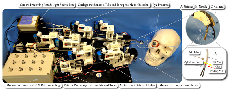
The micro-gripper (see A in Fig. 3) is produced in separate halves with wire Electro-Discharge Machining (EDM). Each half is cut with a thin electrode from a 0.7 mm thick stainless steel sheet. The gripper’s half is composed of a grasping jaw, which is 3.2 mm long, 0.7 mm wide, approximately 0.5 mm thick, and a thin stem that acts as a spring element once the two gripper’s halves are welded together. The stem is approximately 3 mm long and is welded at the base to the opposite jaw’s stem. Welding is realized using a laser micro-welder while holding the jaws angled at approximately 30°. The welded gripper stems act as a spring by maintaining the jaws in an open configuration. When it is pulled back relative to a cylindrical socket, the inner wall of the socket forces the gripper to close. A thin stainless steel wire (diameter 0.2 mm) is welded to the micro-gripper stems to control the relative position of the grasper compared to the socket. On the contrary, the cylindrical socket is glued on the exterior of the inner concentric tube. An illustration of the gripper’s design is shown in Fig. 3.
Fig. 3. The experimental setup, comprising the mechatronics and phantom eye. The eye bulges out of the orbit in the picture for visualization purposes.
The inlet depicts A: the micro-gripper, B: the needle and C: the camera while the illustration shows the design and working principle of the micro-gripper. The NiTi tube and the cylindrical socket are semi-transparent for better visualisation of the SS wire.
Cannulation of the optic nerve is achieved through the second arm, B in Fig. 3. The tip of its inner concentric tube was cut to have a bevel of 45°, allowing its use as a needle.
The vision module was mounted on a NiTi arm via the employment of a holder clip. The clip was produced with a section of stainless steel (SS316) tube. To improve the triangulation and visualisation of the surgical target, the clip was welded to the NiTi tube at an angle of approximately 15°, see C in Fig. 3. In the future, the camera will be directly inserted into a NiTi tube. Currently, it was preferred to maintain it external for simplicity of placement and maintenance.
NiTi tubes were precurved using heat treatment. An aluminum template (Al 2219) with slots/grooves of the desired curvature was machined. Parts of the curving protocol were extracted from different sources in the literature while experimental work went into its fine tuning. A summary of the curving protocol is provided for completeness.
First, it was experimentally found that the template should be preheated to 520 °C for approximately 10 mins to ensure its uniform heating when the tubes are inserted. Next, the tubes are inserted in the preheated template and the assembly is inserted in the oven at 510°C—514°C steady state temperature for 30 mins. Afterwards, the template with the tube is rapidly quenched in cold water for immediate cooling. We observed reliable shape setting for curvatures ranging from 14.5 to 285.7 m-1, and diameters from 1 to 2.8 mm. The final relaxed tube curvature for use in mechanics models was identified using a vector graphics editor to fit a circle on the tube and measure its radius.
To minimise the length of the NiTi tubes, which leads to torsion and “snapping,” NiTi tubes were glued with Loctite 648 and Loctite 7649 to concentric stainless steel (SS) tubes, which are in turn coupled to the motion transmission mechanism described in the next section.
B. Motion Transmission Mechanism
The motion transmission mechanisms that deploy the continuum tools are described herein based on the DoF discussion presented in Section II-A. Fig. 3 shows the multi-arm concentric tube system that was developed to showcase tool deployment in a phantom as a proof of concept. Each tube is held by a carriage that incorporates the tube rotation mechanism. Each carriage is held by a lead screw. It was chosen to use lead screws for the translation of each carriage and tube because of the precise actuation they offer, their affordability, and long-term reliability. For each robotic arm, two lead screws are used for the two tubes that it comprises.
A timing belt is used for each rotational DoF. Even though timing belts can retain the compactness of the system, the backlash that they may effect to the system is crucial. To avoid such an effect, a pretenser is introduced on the upper part of the carriage (see Fig. 3). That part along with an idler add adjustable pretension to the timing belt. Every translational DoF is actuated by a continuous RS motor (SRC SM-S4315R) with a maximum torque of 1.47 Nm while servo motors (DS3235) with maximum torque of 3.43 Nm and range from 0° — 270° are selected for the rotational DoFs. The robot’s control unit in the current setup comprises potentiometers as input elements that permit fine control of the tip’s motion as they allow analogous rotation and intuitive control of the speed insertion (translation) of the tubes. The control board, i.e., an Arduino, can be programmed directly via a PC program to implement complex control in the future.
To monitor the translation of each tube, linear, continuous turn, rotary potentiometers are employed. They are connected to a secondary Arduino and the data are passed to Matlab to estimate each arm’s shape by the standard mechanics models of the literature [6], [16]. Any misalignment in connecting the potentiometers and the motors to lead screws and shafts respectively is absorbed by flexible couplings.
III. Modeling and Workspace Analysis
To validate that the robot can reach the desired workspace and cannulate the optic nerve, the robot was modelled and simulations were run to derive possible rotational and translational inputs respecting the application’s required workspace.
A. CTR Quasi-Static Model
We start with a brief summary of the CTR model first presented in [6], [16]. The following notation is used throughout the article: x, x, and x denote a scalar, a vector, and a matrix, respectively. The prime denotes derivatives with respect to spatial coordinate s.
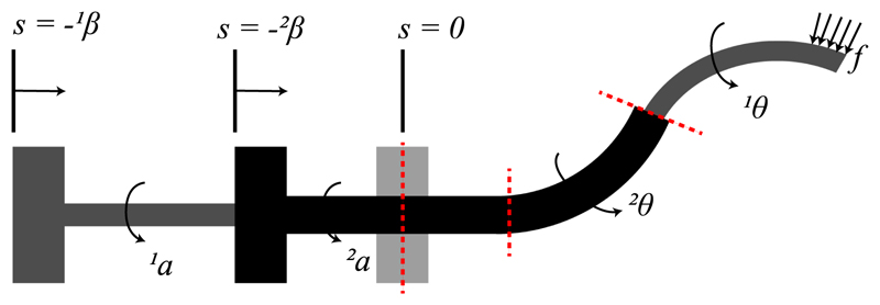
The CTR tubes are modelled as long, slender, onedimensional Cosserat rods endowed with a continuous homogeneous transformation matrix attached to every point on its arc. The shape of each tube is determined by the position vector r(s) : [0,ℓ] → ℝ3, where the coordinate s ∈ [0,ℓ] is the arc length, and ℓ is the tube’s length. The rotation matrix of the frame moving along the tube’s arc is R(s) : [0,l]→ SO(3), representing orientation change and twisting along s. The constitutive equation for calculating the instantaneous curvature of the tubes and the overall robot shape are derived according to [6], [16]. The shape of the robot is derived by computing the shape of the segments that it is composed of. Those segments are identified by splitting the robot at transition points which model the position where the curvature or the number of the tubes changes. At those points, the continuity of shape and internal moment must be enforced (transition points are shown by dashed lines in Fig. 4). To find the deformed shape of all the tubes, it should also be taken into account that at a given time t they must be equal to the curve of a referred tube ri (s). Considering the rotation of the tubes, the angle θi (s) is employed which parameterize the tubes’ twist around z axis following the guidelines introduced in [6].
Fig. 4.
Model of a concentric tube robot. Tubes are grasped at their respective proximal ends. The actuation variables αi (t) and βi (t) denote the proximal base rotation and translation of the i-th tube, respectively. Each tube comprises a straight and a curved part. Angular displacement of tube i at arclength s is denoted by θi (s).
Finally, based on these assumptions, in the absence of external torques, the curvature of tubes is found as follows
| (2a) |
| (2b) |
| (2c) |
where superscript i = 1 ,...,N denotes the i-th tube, with i = 1 corresponding to the innermost tube; subscript n = 1,2,3 denotes the n-th element of a vector; e3 = [0, 0, 1]T is the unit vector aligned with the z-axis of the global coordinate frame; Ui denotes the precurvature of each tube in its reference configuration; θi=ui3 denotes the angle of twist about the local z-axis with respect to global frame; Ki = diag(EiIi, Ei Ii, Gi Ji) is the stiffness matrix for tube i; E is the tube’s Young’s modulus; I is the second moment of inertia; G is the shear modulus; J is the polar moment of inertia; f is any external force applied to the robot. Please note that we drop the (s) notation for simplicity.
The boundary conditions can be specified in terms of tube curvature and the actuators’ values as follows
| (3) |
where the notation (|s=ξ) indicates the value of a variable at arclength of ξ, and ℓi is the length of the i-th tube. Solving (2) and (3) gives the robot backbone curvature and shape. The Boundary Value Problem (BVP) is solved using the fminsearch optimization function of Matlab.
B. Computational & Experimental Workspace Evaluation
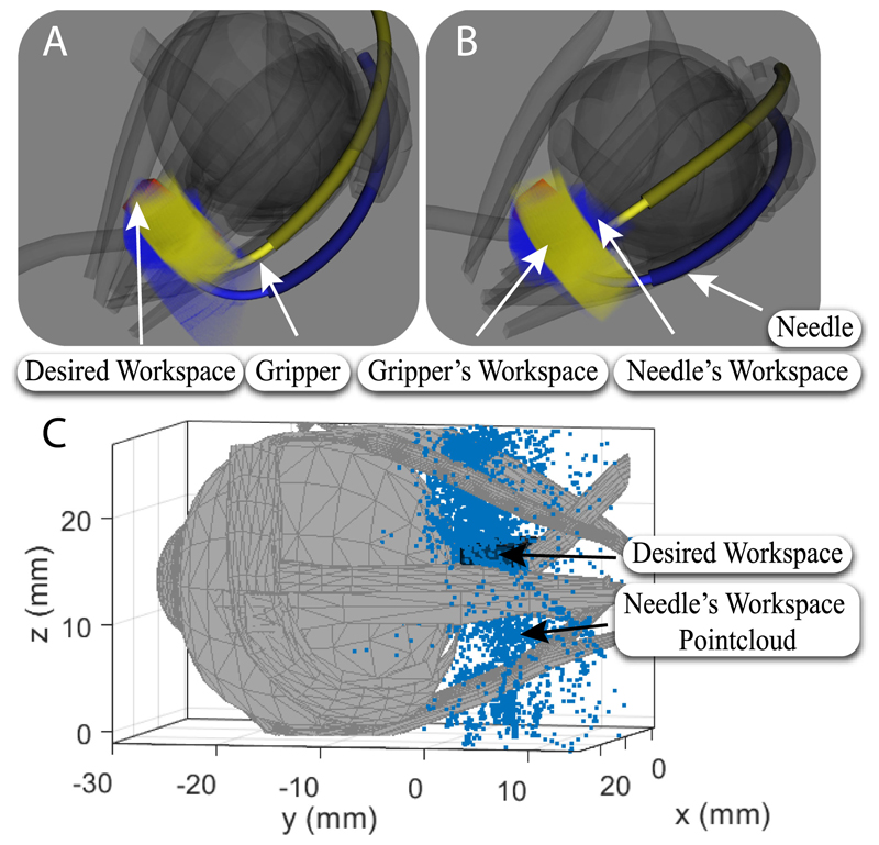
System design was evaluated against the requirements by a detailed computational analysis study of the reachable workspace, employing a modification of the framework presented in [17] and also experimentally via the use of an electromagnetic spatial measurement system. The reachability results for the two manipulator arms are illustrated in Fig. 5. The 3D eye model was segmented from MRI scans and subsequently used to create a realistic phantom for the experimental setup (detailed in Section IV-A).
Fig. 5. Visualization of the reachability of the desired workspace by the concentric tube manipulators.
A-B: Computational analysis results: Yellow, and blue represent the reachability of the micro-gripper, and needle tip, respectively, for the evaluated configuration space, red represents the target workspace which is completely covered. A: Side view of the manipulator’s workspace. B: Top view of the manipulator’s workspace. C: Experimental validation of workspace.
First, the global workspace investigated for reachability (24 mm × 18mm × 18mm) was voxelised into cubes with an edge length of 0.12 mm (200 × 150 × 150 voxels). Each voxel representing an end-effector position was further subdivided into 420 unique rotations, which results in an angular distance of 18° between neighbouring rotations. Each position voxel held the number of orientations that can be achieved at that respective position.
Each tube was rotated and translated within a pre-specified range of values that took into consideration the constraints arising from the collimator and the anatomy; robot tip position and orientation was recorded. For each robot arm’s workspace, 50 × 109 random configurations were evaluated using GPU based sampling described in [18]. This number of samples means in average more than 10,000 random configurations per position voxel were evaluated, and more than 25 random configurations per unique voxel (considering full pose). A position voxel is considered within the workspace if it is reachable by at least one robot configuration.
The outer tube of the left arm was translated by up to 16.7 mm while its rotation was fixed. This was because the whole workspace could be covered by the rotation of only its inner tube due to its high curvature. The inner tube of the same arm was translated by up to 9.8 mm, and rotated from -23° to 5.4° while the inner tube of the right one was translated by 3.3 mm and rotated from -5.2° to 11.9°. The translation of the outer tube of the right arm was up to 8.8 mm and its rotation ranged from -16.4° to 0°. The computational result (see Fig. 5) supports that the designed continuum arms can reach the desired workspace based on the examined set of joint values. In Fig. 5, the gripper’s and needle’s workspace are represented by yellow and blue respectively while the desired workspace, which is fully reachable, is represented in red.
To validate the analysis presented above and that the curvatures and the lengths of the tubes can cannulate the optic nerve, the prototypical robotic needle was translated and rotated while its position was recorded by an electromagnetic (EM) spatial measurement system (NDI Aurora). An EM tracker was firmly secured with tape on the exterior surface of each tube. As a result the inner tube could not be fully retracted into the outer one without restricting though the coverage of the desired workspace. The offset between the EM tracker and the tube axis was taken into account in the form of a constant transformation in the final results. Fig. 5 presents the point-cloud workspace of the needle. It can be seen that the workspace covers a volume of 275 mm3 which is the surgical area of interest. Fig. 5 depicts only the needle’s workspace for clarity. The measurements were recorded during continuous rotation motor operation but with inert translation motors. The former are the distant to the EM sensors and do not affect the measurements. The latter introduce no noise when inert.
IV. Proof-of-Concept Experimentation
The experiments section will demonstrate a meaningful manipulation sequence, derived from the robot mechanics models, that positions the tools along the configurations required to perform ONSF. Our experimental study focuses on the performance evaluation of the needle of the end-effector to cannulate the optic nerve. igh-fidelity components of the eye orbit were developed and fabricated to experimentally evaluate a deployment sequence, as detailed in the following.
A. Fabrication of a High-Fidelity Eye Phantom
A segmented 3D MRI scan of an adult patient’s eye was used as a reference, alongside anatomical drawings. Through the 3D segmentation of the scan, a life-size rigid 3D-printed eye orbit including the optic nerve, rectus and obliques extraocular muscles and their tendons was created for reference on fabrication of the eye phantom.
First, the eye globe (oculus) was isolated from the rest of the 3D-printed structures; it was cast and a mould was created. The shore 2A platinum silicone rubber was selected to model the optic nerve as its stiffness is closer to human’s optic nerve sheath which is E = 0.1 MPa, [19], [20]. The Young’s Modulus of the selected rubber is E = 0.26 MPa according to manufacturer’s data-sheet. The selected rubber, pigmented to the desired color white colour of the sclera, was poured in the mould to replicate the eye in its true dimension. When the silicone cured, the oculus was demoulded and detailed iris and pupil were painted onto it.
Subsequently, the muscles, the common tendinous ring, and the optical nerve were sculpted with plantinum cure silicone shore 2A and pigmented to the desired color following illustrations of the anatomy. A silicone tube with a diameter of approximately 2 mm was used for the fabrication of 2 blood vessel structures: a representation of the 4 vortex veins, and a representation of the ophthalmic artery with 3 branches (the ophthalmic artery, long posterior ciliary arteries and the central retinal artery). It was then coated with platinum cure silicone 2A shore to simulate the color and texture. A fat-like yellow/red color was used to color the artery, while a blue/purple coating was used to simulate the color of the vein. Platinum cure silicone rubber with shore hardness of 2A was used to assemble all components too.
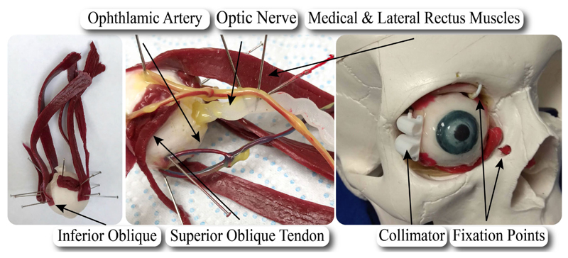
Once the separate components were cured, they were pinned onto their position on the eye and connected with silicone. The common tendinous ring and the muscles were attached, and the nerve and blood vessels were positioned. The completed phantom is shown in Fig. 6, where major elements of the anatomy are illustrated.
Fig. 6. Illustration of the fabricated eye phantom and its elements.
Upon the completion of the eye fabrication, it was installed into the cavity of a commercially available skull. It was fixed by securing the inferior oblique muscle and superior oblique tendon to the orbital wall, while tension was provided via a knot on the optic nerve as it passes into the skull.
B. Experimental Evaluation With Ex Vivo Tissue
To prove that the robot can cannulate the optic nerve, a series of experiments were run on porcine eyes. They have been conducted to evaluate the performance of the robot on real tissue and due to lack of comparative data on the requirements of ONSF in the literature. The tests are: 1) stiffness measurement along the porcine eye and the eye phantom optic nerve, 2) ONS penetration force threshold measurement, and 3) robotic cannulation of the porcine eye optic nerve.
1). Porcine Eye & Eye Phantom Stiffness Measurement
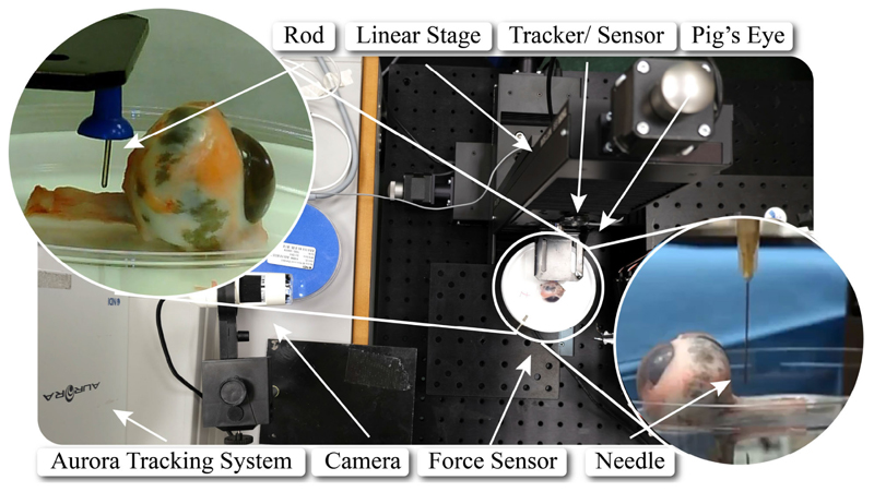
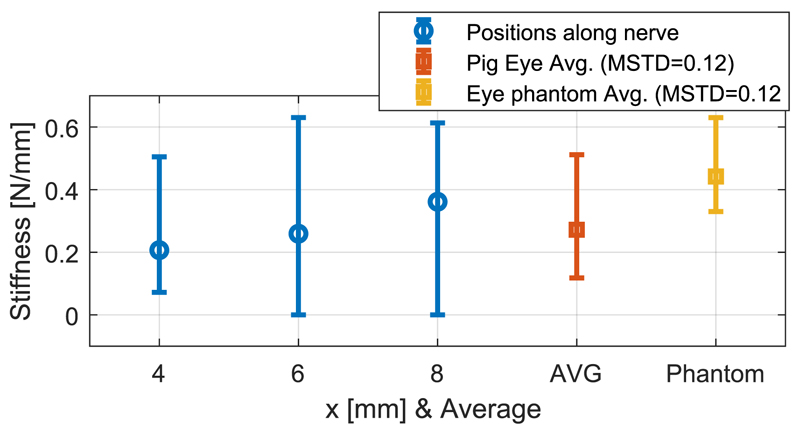
Porcine eye samples acquired from an abattoir were glued to a Petri dish and placed on a 6-axis force sensor (ATI F/T Sensor: Nano17). To measure the stiffness of porcine optic nerve, a blunt pin (1.12 mm diameter) was employed to deform it by 1 mm in 3 different positions at 4, 6, and 8 mm distance from the posterior part of the eye globe for 10 different eye samples (see Fig. 7). These positions were chosen according to the desired surgical workspace. The force exerted on the optic nerve was measured by the force sensor, and the motion of the pin was recorded via an electromagnetic spatial measurement system. It was found that the stiffness of porcine optic nerve increases along the nerve (as observed also on human tissue), and had an overall mean value of 0.27 N/mm (see Fig. 8).
Fig. 7. The experimental setup, comprising the porcine eye, the force sensor, the linear stage, and the tracking system.
Fig. 8.
The stiffness of the porcine optic nerve for 4, 6, and 8 mm distance from the eye globe, average stiffness along the nerve (AVG), and the average stiffness of the high-fidelity eye phantom optic nerve.
The same experiment was carried out 5 times on the fabricated phantom. The stiffness of its nerve remains almost constant along it, with a mean of 0.44 N/mm, due to its homogeneous fabrication (see Fig. 8). It is on the same order of magnitude as the stiffness of the porcine optic nerve, making the phantom a good model for comparison with ex vivo data.
2). Porcine Optic Nerve Penetration Threshold
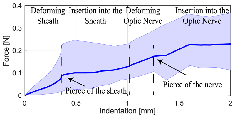
To measure the force required to cannulate the optic nerve, a similar experiment as in the previous case was carried out with a needle (Microlance 3,0.5 × 25 mm) on 4 different porcine eye samples. The averaged penetration force vs. indentation plot in Fig. 9 shows the deformation and penetration regions of different layers of the nerve tissue. The shaded area presents the minimum and maximum values recorded for each penetration value in the trials. The nerve sheath deformed until the force reached ≈ 0.1 N at ≈ 0.4 mm indentation where the sheath was teared, compared to 23.51 mN in the case of vitrectomy [12]. The needle penetrated further the tissue until it reached the nerve itself at ≈1 mm indentation, which is consistent with clinical measurements of the sheath thickness [19]. The nerve deflected ≈ 0.2 mm further where the needle pierced it with ≈ 0.2 N force. The robot needs to exert such forces with appropriate needle attack angle to perform oNSF.
Fig. 9. Mean value of insertion force versus displacement from experiments on 4 porcine optic nerves, and maximum/ minimum thresholds for measured values.
3). Robotic Cannulation of Optic Nerve
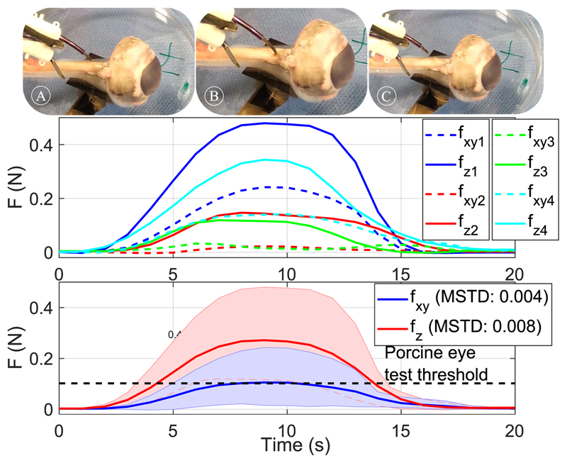
Fig. 10(top) shows cannulation of porcine optic nerve with the robot’s sharpened tip. Four porcine eye samples, glued to a Petri dish and placed on the force sensor, were used to test the robotic cannulation procedure. The robotic needle was extended until we could visually confirm penetration of the nerve sheath. Fig. 10(middle) presents the force values exerted by the robotic needle for each trial starting from the time when the robot tip contacts the tissue, identified as a small spike in the force sensor readings. Fig. 10(bottom) shows the filtered averaged values and the maximum and minimum threshold for the measured values. In all cases, penetration of the optic nerve was visually confirmed. Please note that the optic nerve was accessed from the opposite direction compared to a real scenario to decouple the compressing effect that the collimator might have on the porcine eye from the exercised forces. To simulate the resistance that the skull’s bone applies on the collimator, the collimator was held fixed at a mirror distance from the sclera. The measured forces are higher than the mean penetration threshold shown in Fig. 9. Possible reasons for this difference are the deviation of the robot tip attack angle, the reduced sharpness compared to a standard needle and the different indentation values.
Fig. 10. Penetration of the optic nerve by the robot’s needle.
Top-A-C indicate cannulation of the optic nerve. A: Approach of the robotic needle, B: Cannulation of the optic nerve, C: Retraction of the robotic needle. The graph presents the mean value of the vertical and lateral forces as measured by the force sensor and the maximum and minimum recorded values between different trials. Middle-measured values for 4 trials. Bottom-averaged value and maximum and minimum threshold for measured values of lateral (fxy) and penetrating (fz) forces.
C. Experimental & Simulation Study With Eye Phantom
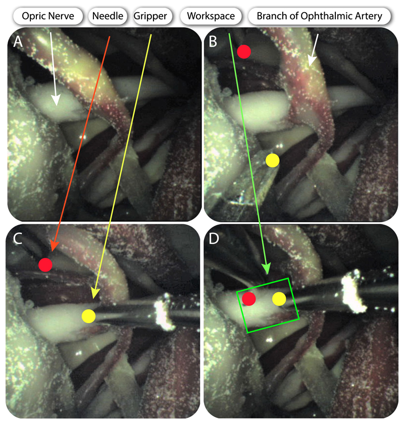
To prove the concept of accessing the eye orbit and perform an intervention on the optic nerve, the tools that were described in Section II-A were actuated to perform ONSF on the high-fidelity eye phantom. Fig. 6 shows the posterior part of the eye upon its fixation into the skull, while the collimator is also illustrated. The tool guide is placed between the lateral and superior rectus. Next, the arms and the camera are inserted in the collimator, either automatically or manually using surgical tweezers, and access the orbit. The tube that holds the camera is manipulated to illuminate the orbit and reach the FoV that visualises the desired workspace and tool access points. The arm that holds the micro-gripper grasps the optic nerve to hold it steady during cannulation. Upon the grasping of the optic nerve, the second arm with the bevelled tip approaches the surgical area of interest and cannulates the optic nerve. The tools are then retracted and the robot can be placed away from the skull. Fig. 11 illustrates the deployment of the tools as captured from the camera’s viewpoint. Both tools operated in the desired workspace as the workspace analysis predicted.
Fig. 11. Deployment of the manipulators and the camera for OSNF.
A–D indicate cannulation of the optic nerve. Brightness was enhanced for clarity. A: Visualization of the optic nerve from the camera. B: Both manipulators come into sight. C: The right manipulator (micro-gripper) grasps the optic nerve. D:: The left manipulator (bevel tip) approaches the optic nerve.
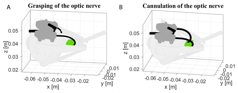
The recorded rotation and translation of each tube were imported as initial conditions to the theoretical mechanics model of Section III, to verify the theoretical model framework. Fig. 12 shows the grasping and cannulation of the optic nerve as they were derived via simulations by moving the arms according to the experimental inputs of Fig. 11. The theoretical model confirms that both arms can operate in the desired workspace as it was validated by the experimental results. Fig. 11 shows successful deployment of the arms in accordance with the prediction of the arm’s shape based on the simulation results in Fig. 12(A)-(B).
Fig. 12. Grasping (A), cannulation (B) of the optic nerve as derived from the theoretical model based on encoder readings from the experiment in Fig. 11.
V. Conclusion
In this article, we presented our work on the development of a multi-arm CTR for deep orbital interventions, emphasizing on the treatment of ONSF. The design of the system considers the limitations and constraints that occur in ophthalmic surgical procedures of the optic nerve, i.e., limited workspace, high radius of curvatures, bimanual manipulation, and visualization of the tools and the area of surgical interest. It was shown that the proposed system can navigate periocularly the eye and perform the desired procedure in our theoretical simulation and experimental study, and in comparison with ex vivo porcine tissue experimental evaluation. Future work includes positioning the motors at the rear of the system, to ensure they are as distant as possible from the robot’s tip, improving the design of the end effector, planning multi-arm collaborations for ONSF using the presented setup and employing tissue from a cadaver for more realistic experiments.
Acknowledgment
The authors would like to thank Dr. Sánchez for drawing Fig. 2, Dr. Liu for loaning the force sensor used in this study, and Dr. Vasilopoulos for his help with the porcine tests.
Footnotes
This letter has supplementary downloadable material available at http://ieeexplore.ieee.org, provided by the authors.
Contributor Information
Zisos Mitros, Robotics and Vision in Medicine (RViM) Lab, School of Biomedical Engineering & Imaging Sciences, King’s College London, London E14 3WF, U.K.; Wellcome/EPSRC Centre for Interventional and Surgical Sciences, University College London, London WC1E 6BT, U.K..
Seyedmohammadhadi Sadati, Email: smh_sadati@kcl.ac.uk, Robotics and Vision in Medicine (RViM) Lab, School of Biomedical Engineering & Imaging Sciences, King’s College London, London E14 3WF, U.K..
Carlo Seneci, Email: carlo.seneci@kcl.ac.uk, Robotics and Vision in Medicine (RViM) Lab, School of Biomedical Engineering & Imaging Sciences, King’s College London, London E14 3WF, U.K..
Edward Bloch, Email: edward.bloch@nhs.net, Wellcome/EPSRC Centre for Interventional and Surgical Sciences, University College London, London WC1E 6BT, U.K.; Moorfields Eye Hospital, London EC1V 2PD, U.K..
Konrad Leibrandt, Email: k.leibrandt12@imperial.ac.uk, Wellcome/EPSRC Centre for Interventional and Surgical Sciences, University College London, London WC1E 6BT, U.K..
Mohsen Khadem, Email: mohsen.khadem@ed.ac.uk, School of Informatics, University of Edinburgh, Edinburgh EH8 9AB, U.K..
Lyndon da Cruz, Email: l.cruz@ucl.ac.uk, Wellcome/EPSRC Centre for Interventional and Surgical Sciences, University College London, London WC1E 6BT, U.K.; Moorfields Eye Hospital, London EC1V 2PD, U.K..
Christos Bergeles, Email: christos.bergeles@kcl.ac.uk, Robotics and Vision in Medicine (RViM) Lab, School of Biomedical Engineering & Imaging Sciences, King’s College London, London E14 3WF, U.K..
References
- [1].Mukherjee N, El-Dairi MA, Bhatt MT. Optic nerve sheath fenestration—Indications and techniques. US Ophthalmic Rev. 2013 Jul;6(2):125–132. [Google Scholar]
- [2].Yaqub M, Mehboob MA, Ul Islam Q. Efficacy and safety of optic nerve sheath fenestration in patients with raised intracranial pressure. Pakistan J Med Sci. 2017;33(2):471–475. doi: 10.12669/pjms.332.11937. [DOI] [PMC free article] [PubMed] [Google Scholar]
- [3].Sergott RC, Savino PJ, Bosley TM. Optic nerve sheath decompression: A clinical review and proposed pathophysiologic mechanism. Aust N Z J Ophthalmol. 1990;18(4):365–373. doi: 10.1111/j.1442-9071.1990.tb01819.x. [DOI] [PubMed] [Google Scholar]
- [4].Friedman DI, Jacobson DM. Idiopathic intracranial hypertension. J NeuroOphthalmology. 2004;24(2):138–145. doi: 10.1097/00041327-200406000-00009. [DOI] [PubMed] [Google Scholar]
- [5].Burgner-Kahrs J, Rucker DC, Choset H. Continuum robots for medical applications: A survey. IEEE Trans Robot. 2015 Dec;31(6):1261–1280. [Google Scholar]
- [6].Dupont PE, Lock J, Itkowitz B, Butler E. Design and control of concentric-tube robots. IEEE Trans Robot. 2010 Apr;26(2):209–225. doi: 10.1109/TRO.2009.2035740. [DOI] [PMC free article] [PubMed] [Google Scholar]
- [7].Webster RJ, III, Romano JM, Cowan NJ. Mechanics of precurved-tube continuum robots. IEEE Trans Robot. 2009 Feb;25(1):67–78. [Google Scholar]
- [8].Lin F, Bergeles C, Yang G. Biometry-based concentric tubes robot for vitreoretinal surgery; Proc 37th Annu Int Conf IEEE Eng Med Biol Soc; 2015. Aug, pp. 5280–5284. [DOI] [PubMed] [Google Scholar]
- [9].Modes V, Burgner-Kahrs J. Calibration of concentric tube continuum robots: Automatic alignment of precurved elastic tubes. IEEE Robot Autom Lett. 2020 Jan;5(1):103–110. [Google Scholar]
- [10].Fagogenis G, et al. Autonomous robotic intracardiac catheter navigation using haptic vision. Sci Robot. 2019;4(29):eaaw1977. doi: 10.1126/scirobotics.aaw1977. Paper. [DOI] [PMC free article] [PubMed] [Google Scholar]
- [11].Burgner J, et al. A telerobotic system for transnasal surgery. IEEE/ASME Trans Mechatronics. 2014 Jun;19(3):996–1006. doi: 10.1109/TMECH.2013.2265804. [DOI] [PMC free article] [PubMed] [Google Scholar]
- [12].Farooq MU, Xu B, Ko SY. A concentric tube-based 4-DOF puncturing needle with a novel miniaturized actuation system for vitrectomy. BioMed Eng OnLine. 2019;18(46):1–16. doi: 10.1186/s12938-019-0666-x. [DOI] [PMC free article] [PubMed] [Google Scholar]
- [13].Morimoto TK, Greer JD, Hawkes EW, Hsieh MH, Okamura AM. Toward the design of personalized continuum surgical robots. Ann Biomed Eng. 2018 Oct;46(10):1522–1533. doi: 10.1007/s10439-018-2062-2. [DOI] [PMC free article] [PubMed] [Google Scholar]
- [14].Beckerman I, Gottlieb P, Vaiman M. Variations in eyeball diameters of the healthy adults. J Ophthalmology. 2014 Nov;:1–5. doi: 10.1155/2014/503645. [DOI] [PMC free article] [PubMed] [Google Scholar]
- [15].Gilbert HB, Webster RJ., III Rapid, reliable shape setting of superelastic nitinol for prototyping robots. IEEE Robot Autom Lett. 2016 Jan;1(1):98–105. doi: 10.1109/LRA.2015.2507706. [DOI] [PMC free article] [PubMed] [Google Scholar]
- [16].Rucker DC, Jones BA, Webster RJ., III A geometrically exact model for externally loaded concentric-tube continuum robots. IEEE Trans Robot. 2010 Oct;26(5):769–780. doi: 10.1109/TRO.2010.2062570. [DOI] [PMC free article] [PubMed] [Google Scholar]
- [17].Burgner J, Gilbert HB, Webster RJ., III On the computational design of concentric tube robots: Incorporatingvolume-based objectives. Proc IEEE Int Conf Robot Autom; 2013. pp. 1193–1198. [Google Scholar]
- [18].Leibrandt K, Bergeles C, Yang GZ. Implicit active constraints for concentric tube robots based on analysis of the safe and dexterous workspace. Proc IEEE/RSJ Int Conf Intell Robots Syst; 2017. pp. 193–200. [Google Scholar]
- [19].Hua Y, Voorhees AP, Sigal IA. Cerebrospinal fluid pressure: Revisiting factors influencing optic nerve head biomechanics. Investigative Ophthalmology Vis Sci. 2018 Jan;59(1):154–165. doi: 10.1167/iovs.17-22488. [DOI] [PMC free article] [PubMed] [Google Scholar]
- [20].Feola AJ, Nelson ES, Myers J, Ethier CR, Samuels BC. The impact of choroidal swelling on optic nerve head deformation. Investigative Ophthalmology Vis Sci. 2018 Aug;59(10):4172–4181. doi: 10.1167/iovs.18-24463. [DOI] [PubMed] [Google Scholar]


