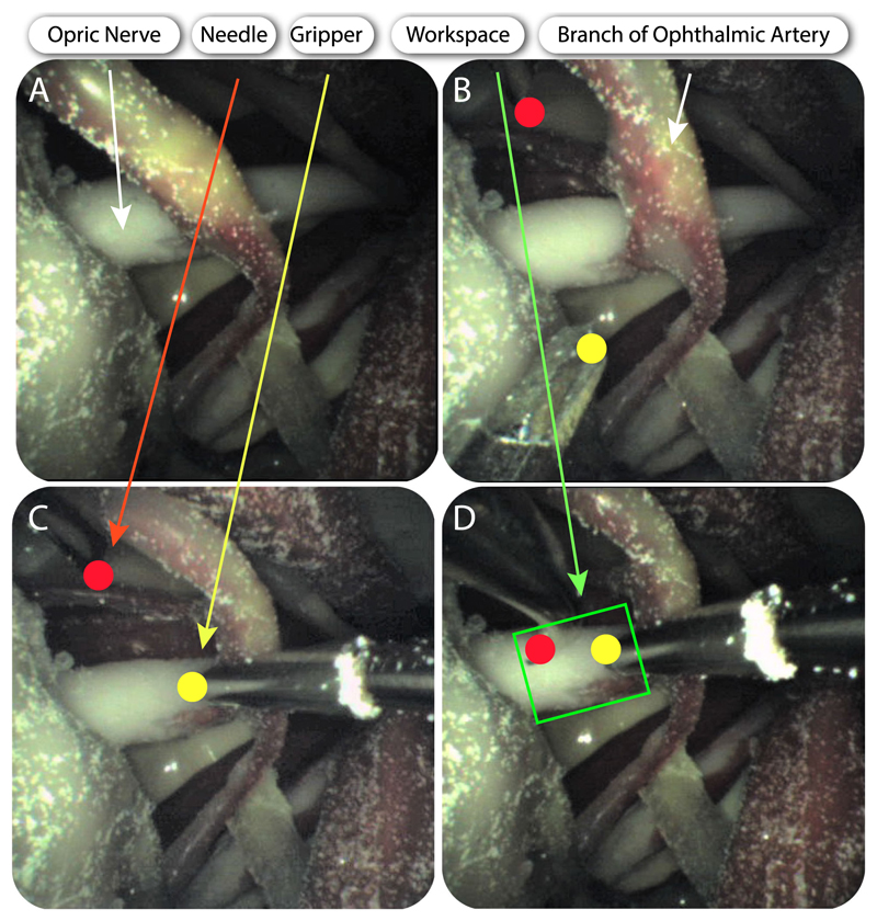
Fig. 11. Deployment of the manipulators and the camera for OSNF.
A–D indicate cannulation of the optic nerve. Brightness was enhanced for clarity. A: Visualization of the optic nerve from the camera. B: Both manipulators come into sight. C: The right manipulator (micro-gripper) grasps the optic nerve. D:: The left manipulator (bevel tip) approaches the optic nerve.

