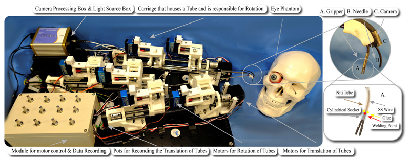
Fig. 3. The experimental setup, comprising the mechatronics and phantom eye. The eye bulges out of the orbit in the picture for visualization purposes.
The inlet depicts A: the micro-gripper, B: the needle and C: the camera while the illustration shows the design and working principle of the micro-gripper. The NiTi tube and the cylindrical socket are semi-transparent for better visualisation of the SS wire.

