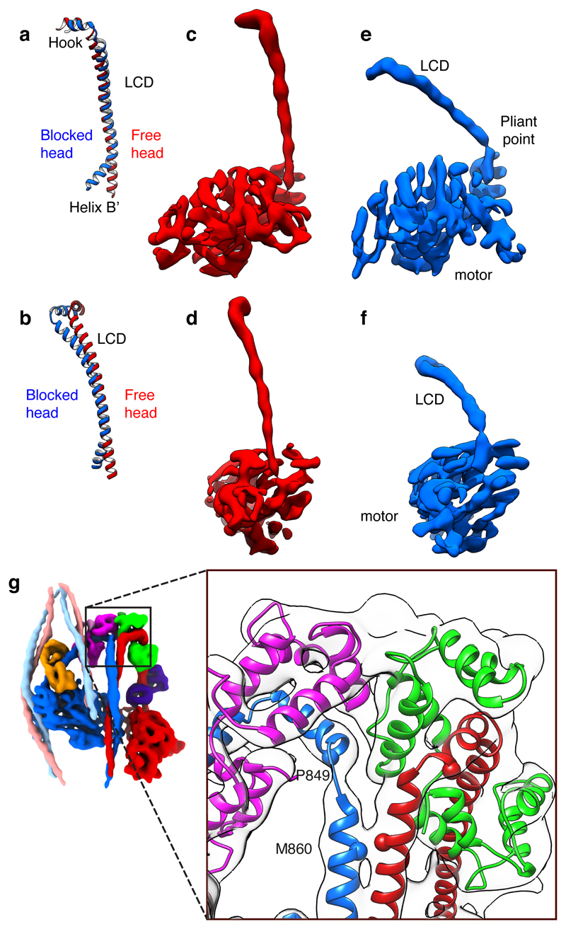
Figure 3. The levers of free- and blocked-heads and head-tail junction.
a, b, Blocked and free-head lever heavy chain pseudo-atomic models superposed on backbone atoms of the ELC-binding IQ motif, oriented to match panels c-f. Heavy chain shown runs from Helix B’ of converter to hook helix of LCD. c, d, Two orthogonal views of density map of free-head motor plus LCD with LCs omitted for clarity, and e, f, corresponding views of blocked-head motor. Threshold for density maps chosen to illustrate the narrow density at the pliant point of the blocked-head motor. g, Structure of the head-tail junction with atomic model fitted into electron density map; colours as Fig. 1. Cα of invariant Pro849 of hook helix and Met860 at start of coiled coil shown as spheres. Contour level for c–f 0.594; for g 0.475.

