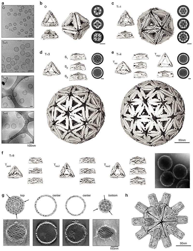
Fig. 2. Structures of shells and of shell subunits.
(a) Cryo-EM micrographs of assembled shells in free-standing ice (O, T=1) and on lacey carbon grids with carbon support (T=3, T=4). (b to e) Cryo-EM reconstructions of shell subunits and fully assembled shells (octahedron to T=4 shells). The two-dimensional class averages show assembled shells from different orientations, scale bars 50nm. See also Supplementary Video 1-4. (f) Cryo-EM reconstructions of the three triangles assembling into a T=9 shell and negatively stained EM micrograph of assembled shells. (g) Comparison of slices through a model T=9 shell to slices of a tomogram calculated from an EM tilt series. The arrows indicate the positions of pentamers within the T=9 shell. See also Supplementary Video 5. (h) Cryo-EM reconstruction of a T=1 shell with a central-cavity blocking DNA “spacer” module. See also Supplementary Video 8.

