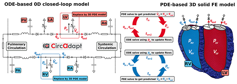
Figure 3.
Schematic showing the coupling of the 0D ODE model, represented by the electrical equivalent circuit, to the 3D PDE model, represented by the FE mesh. In this case the ventricles (LV, RV) in the lumped model are replaced by 3D PDEs, while the atria (LA, RA) are modeled as lumped cavities in the CircAdapt model. Volume changes of the 3D cavities , are driven by flow q • of blood over valves and outlets computed by the 0D model. In turn, updated pressures p LV and p RV are used as an input to the lumped model in the next time step t n+1. The opening and closure of valves is only modeled in the lumped model and in the 3D model triangulated membranes are used to close the LV and RV cavities. Red colors indicate oxygenated and blue colors de-oxygenated blood. (For interpretation of the references to color in this figure legend, the reader is referred to the web version of this article.)

