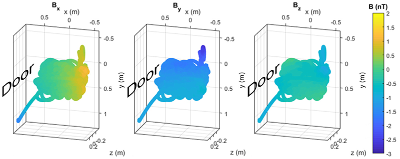
Fig. 4.
Background magnetic field in the Magnetic Shields Limited (MSL) MSR at UCL at the mean OPM position during the first run of the triaxial experiment, according to a 3rd order real spherical harmonic model. The three columns are the three magnetic field components. In each, the direction of the MSR door is indicated. The graphs are oriented to be representative of the room such that down the page is nearer to the ground in the room. The two trails coming out of the main space - bottom left and top right - are, respectively, caused by the magnetometer being picked up off the table at the start of the experiment and moving it nearer the camera (to see how this affected the field). The equivalent figure for the second run of this experiment and for the OP-MEG experiment is shown in Supplementary Fig. 3.

