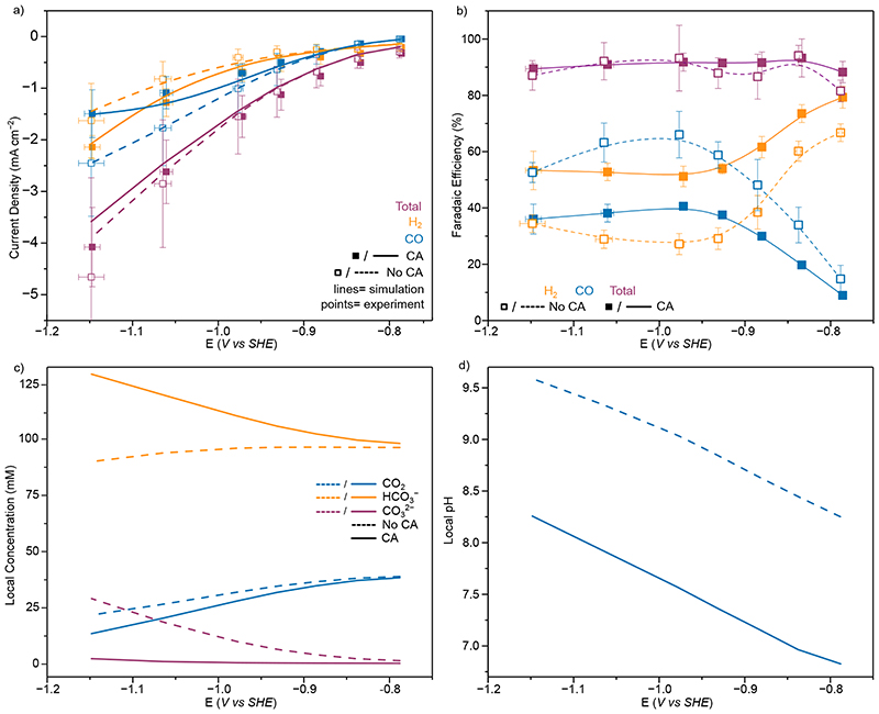
Figure 6.
CO2R on Au with and without CA (20 µM) in 0.1 M KHCO3 solution (a) Experimental (points) and simulated (lines) total (purple) and partial current densities for H2 (orange) and CO (blue) from controlled potential electrolysis of Au. Points represent averages of at least three independent stepped-chronoamperometry experiments, where filled points were with CA (20 µM) in solution and unfilled without. (b) Experimental H2 (orange), CO (blue) and total (purple) FE. Lines added to guide the eye and do not represent fits (c) Simulated concentrations at the electrode surface for CO2 (blue), HCO3 − (orange) and CO3 2− (purple) with (solid lines) and without (dashed lines) CA in solution. (d) Electrode surface pH from FEM with (solid lines) and without (dashed lines) CA in solution. Points represent averages of at least three independent stepped-chronoamperometry experiments, where filled points were with CA immobilised on the electrode surface and unfilled without. Y Error bars represent the standard deviation of measured currents and X the standard deviation in applied potential due to the ohmic drop correction of multiple measurements(n=4). All experiments conducted at 20°C

