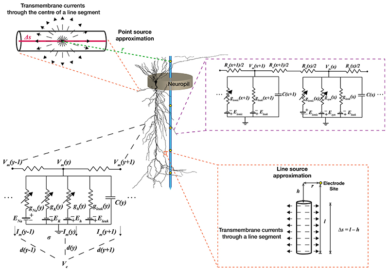
Fig. 4. Approaches to account for active dendrites in LFP computation.
Center: A single electrode with multiple recording sites in the center of a cylindrical neuropil of a population of morphologically realistic pyramidal neurons. Note, while a single morphology is depicted here for simplicity, a heterogeneous set of morphologies should be employed to account for the underlying structural heterogeneity. Top Left: Point source approximation for modeling LFP. Bottom Right: Line source approximation for modeling LFP. Top Right: A representation of conductance-based mutli-compartmental model depicting how to account for location-dependent expression of passive leak, active (voltage-gated) ionic, and synaptic conductances. Bottom Left: A representation of a single compartment within the morphology and the transmembrane currents generated through it due to the presence of active and passive conductances. These transmembrane currents are used for computing LFPs. Symbols used: r: radial distance; σ: macroscopic extracellular conductivity; l,h: longitudinal distance from the beginning and end of the line respectively; Δs: length of line segment; Vm: intracellular membrane potential; Im: transmembrane current; x/y: location variables; Ra: axial resistance; g: conductance (subscript represents the type of conductance); E: reversal potential (subscript represents the type of conductance); C: capacitance; d: distance; Ve: extracellular potential.

