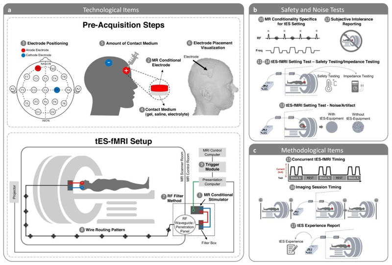
Figure 5. Scheme of the concurrent tES-fMRI approach in the context of the ContES checklist.
(a) Summary of technological considerations. MR conditional stimulator (1, item 1.1) is connected to the head through RF waveguide or RF penetration panel (7, item 1.7). Box cable should be aligned with the wall of the scanner room and run parallel to the bore axis (8, item 1.8). MR conditional stimulator is connected to the outer filter box or RF band-stop filter adapter as well as to the presentation computer trigger output cable. Synchronization module (9, item 1.9) should be connected to the presentation computer as well as to the MRI control computer. Electrode positioning (3, item 1.3) is used to accurately stimulate cortical target regions and exert neuromodulatory effects. A method allowing quantification of contact medium (e.g., syringes) should be used to achieve a consistent and appropriate amount of contact medium (5, item 1.5). MR conditional skin-electrode (e.g., saline solution, conductive paste, gel) (2, item 1.2) is used to facilitate delivery of current to the scalp (4, item 1.4). Electrode placement visualization can be used to reproducibly center each electrode on the head so that intrascanner stimulation allows verification of correct positioning of the electrodes on the head (6, item 1.6). (b) Summary of safety considerations. MR Conditionality Specifics for tES Setting include the technical specifications of the MR scanner, the applied fMRI sequences, and the used tES settings and configuration to fall within the specifics of MR conditionality based on tES manufacturer guideline (10, item 2.1). The Safety of the tES-fMRI Setting includes electrode temperature testing, electric current tolerance testing, etc. with real human subjects or phantoms (11, item 2.2). tES-fMRI Setting Test − Subjective Intolerance Reporting shows the number of cases that have not tolerated the tES-fMRI session (12, item 2.3). tES-fMRI Setting Test - Noise/Artifact shows the noise/artifact induced by the tES setting in the fMRI signal with real human subjects or phantoms before starting the study (13, item 2.4). The impedance is monitored before entering the scanner room and/or in the scanner room and/or inside the scanner and/or during scanning (14, item 2.5). (c) Summary of methodological considerations. Concurrent tES-fMRI Timing shows the timing of concurrent tES within the fMRI paradigm (15, item 3.1). Imaging Session Timing shows the imaging events before and after concurrent tES-fMRI and respective sequences (16, item 3.2). tES Experience Report includes the assessment of the subjective experience of receiving tES inside the scanner (17, item 3.3).

