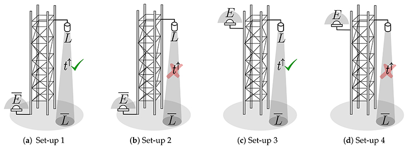
Figure 5.
Diagrams in (a–d) corresponding to the instrument set–up configurations (1), (2), (3) and (4), respectively, described in Section 4.1. (d) represents the common configuration of tower–mounted instruments to measure SIF at tower–scale. In some cases, downward looking sensors mounted at the tower’s top allow multi–angular data collections. Down–welling solar irradiance is typically acquired with upward looking hemispherical or conical systems or by measuring a reference panel with a downward looking sensor. Here t↑ is the upward atmospheric transmittance.

