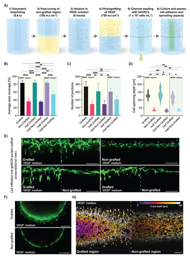
Figure 6. Photografting functional VEGF growth factor as proof-of-concept assay to guide endothelial cell adhesion, interconnectivity, and sprouting.
A) Schematic diagram of the sterile process with which VEGF was photografted onto half of a vascular chip model consisting of a central channel within a gelNOR cylinder. B) Average area coverage and C) number of junctions of interconnected HUVEC clusters in the VEGF-grafted and nongrafted regions of the vascular chip cultured in VEGF-free and VEGF-supplemented medium after 3 days in culture (n = 3). D) Average HUVEC spanning depth from the channel wall into the VEGF-grafted and nongrafted regions of the vascular chip, cultured in VEGF-free and VEGF-supplemented medium after 3 days in culture (n = 3). E) Confocal images of horizontal cross-sections of the channel wall of the vascular chip seeded with HUVECs, showing various degrees of cell sprouting into the printed hydrogel. F) Confocal images of the vertical cross-section of the seeded vascular chip channel in grafted and nongrafted regions cultured in VEGF-free medium. G) Tile scan maximum projection image of a confocal z-stack, the vascular tube showing the boundary between the grafted and nongrafted regions (indicated by a dotted line). The color code indicates the z-axis depth, depicting how cells in all imaged layers can sprout in the surrounding hydrogel matrix. Scale bars = 250 μm. * = p < 0.05, ** = p < 0.01, *** = p < 0.001, **** = p < 0.0001.

