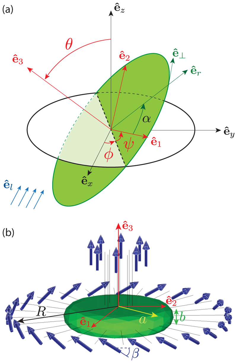
Fig. 4. Details of computational geometry.
(a) Coordinates system and Euler angles. The frame (êx, êy, êz) is attached to the laboratory; the frame (ê1, ê2, ê3) is attached to the Gonium body (green disk), with ê3 the symmetry axis and (ê1, ê2) in the body plane. Euler angles (θ, ϕ, ψ) relate the two frames: by definition, θ is the angle between êz and ê3, ϕ is the angle from êx to the line of nodes (dotted line), and ψ is the angle from the line of nodes to ê1. In the Gonium body plane (ê1, ê2), the flagella are labeled by the angle α, with (êr, ê⊥) the corresponding local frame such that cos α = ê1 · êr. For the computation of the phototactic response, we assume the light is incident along êl = − êx (blue arrows). (b) Gonium geometry for simulations. The body (in green) is a thick disk with radius a = 20 µm and thickness b = 8 µm. Flagella (length 20 µm) associated with a point force 20 µm away from the cell body are attached to the body. The 8 central flagella generate thrust while the 24 peripheral ones are tilted by β ≃ 30° and generate both thrust and rotation.

