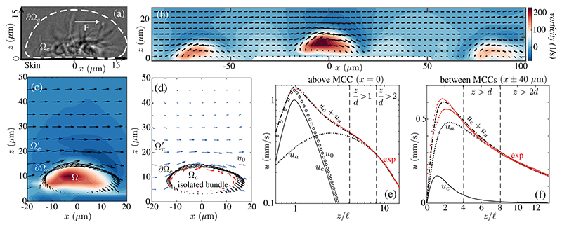
Fig. 2. Flow fields.
(a) Lateral view of MCC showing (dashed) path of cilia tips and force F. (b) Experimental velocity field and vorticity in plane normal to skin near several MCCs. (c) Near an MCC, as in (b), with direction of cilia tip motion (black arrows) on ∂Ωc.(d) Estimated flow field u0 for an isolated MCC (blue arrows): Point forces (red arrows) are used to fit velocity near cilia tips. Lateral velocity at (e) x, y (0, 0) and (f) (±40 μm, 0) in experiment (exp) and theory, with u0 driven by an isolated bundle and uc by a bundle exposed to endogenous flow ua (see also Figs. S2–S4 [29]).

